Installation and Assembly
4-10 User Manual
DMR V4C 3.3 (User Manual) V-4 06-May-2022
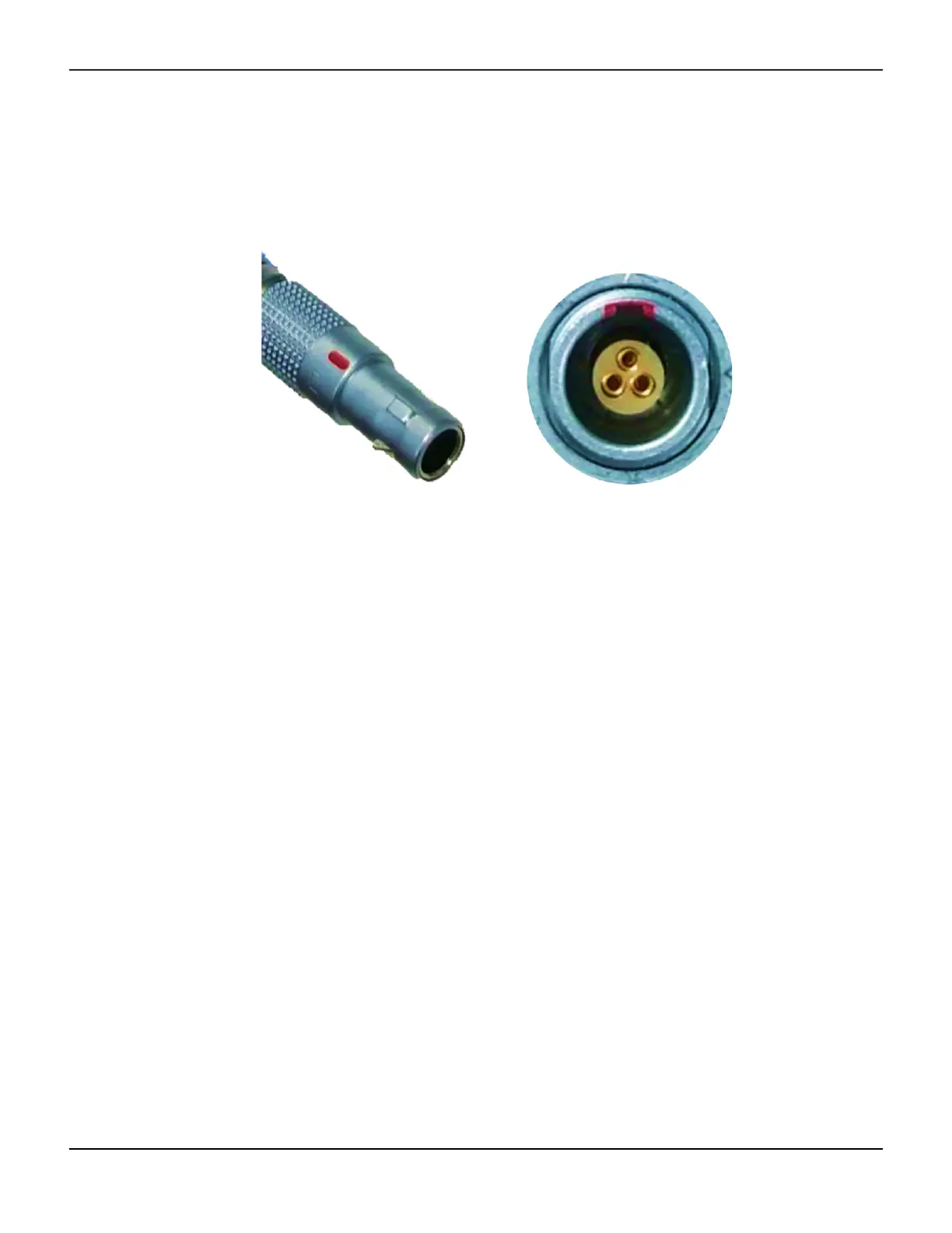
8. Refer to Figure 4-8. Install the O2E electrical connecting cable (2) from the compatible ventilator O2E
port to the V4C-O2E Oxygen Mixer. Refer to Figure 4-11. When connecting the cable, line up the red
marking on the cable’s connector with the red marked notch on the O2E port to ensure the correct
orientation.
Figure4-11.Red markings on the electrical cable and O2E port
Caution:
Connection of the cable between the Oxygen Mixer and the ventilator begins power delivery
to the V4C-O2E Oxygen Mixer automatically when the ventilator enters an active ventilation
state.
Caution:
When attaching the cable to its ports, failure to line up the red markings before applying force,
could lead to damage of the cable pins.
Note:
Both ends of the cable are identical and the cable can be attached in either orientation.
9. Refer to Figure 4-8. Confirm that the air intake filter (3) is installed in the V4C-O2E Oxygen Mixer.
Note:
If the air intake filter is missing, incorrectly installed, soiled, or damaged refer to Section 7, Routine
Maintenance for instructions on replacing it.
10. Confirm that the low pressure oxygen port of the compatible ventilator does not have an oxygen
source attached. Using the V4C-O2E Oxygen Mixer and the low-pressure oxygen port of the ventilator
simultaneously could impact the ventilator's function.
11. Refer to Figure 4-8. Connect the hex nut side of the oxygen hose to the oxygen inlet, located on the
oxygen inlet module (4). Connect the opposite end of the hose to the oxygen supply.