1. Open the carton and stand the tiller on end so you can
see the underside. Fasteners required for assembly are
included. The bolts in the assembly drawing are label-
led (M8 or M10) for the metric diameters and length is
given in millimetres.
If a sulky or utility cart is to be hitched to the tractor, as-
semble the depth gauge bar in a position 180 degrees
from that in the drawing.
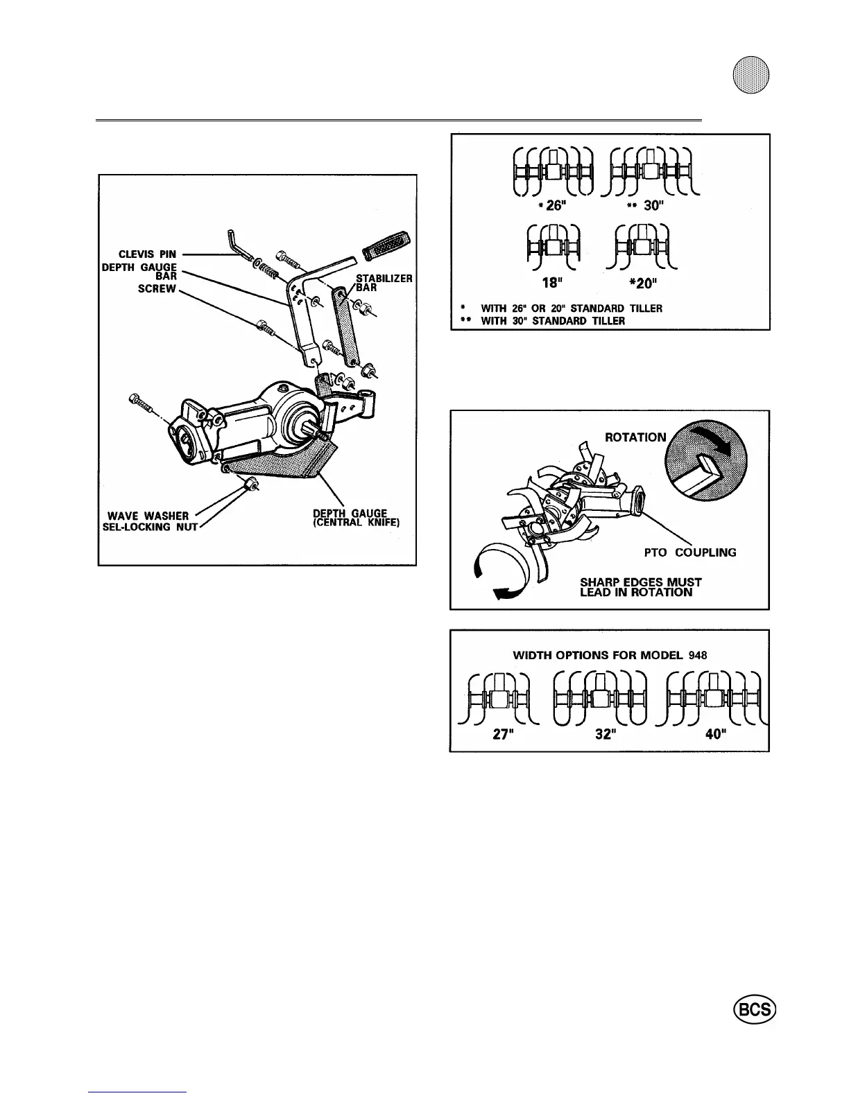
2. Use the self-locking nut to fasten the depth gauge to
the gear housing. Install the flange nut at the stabilizer
bar bottom connection.
3. The depth gauge and stabilizer bar protrude through
the top of the tiller housing. The bar is bolted to the bra-
ckets. The gauge is pinned with the clevis pin and "hair-
pin". Tighten all nuts.
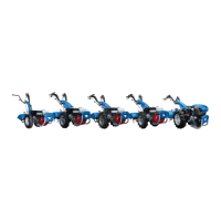
WIDTH OF TILTH
IMPORTANT
When changing sets of tines, it is important to keep
the tines in place on one side for use as a model while
changing tines on the other.
Do not mount the tines backwards on the flange.
SINGLE ROW ATTACHMENT FOR 710, 718, 722, 732
(or converted 852):
Available sizes are 18", 20", 26" and 30".
SINGLE ROW ATTACHMENT FOR MODEL 948:
This comes preassembled for a 32" tilling width. The
width can be increased to 40" or decreased to 27" by
adding or removing flanges of tines, and by changing
the tines to bend inward or outward (see drawing).
TILLING DEPTH ADJUSTMENT
The procedure is the opposite of what many people first
would believe. For the deepest soil penetration, you rai-
se the depth controlling "knife" by pinning the bar in the
bottom hole (see drawing).
37
3