ENGLISH
20 BD LASER MAX Man. cod. B409652FG Class C Solutions Group
MAINTENANCE, DISMANTLING AND DISPOSAL
9.2.7 Inspecting and replacing the fuses
The BD LASER MAX key duplicating machine is equipped with 2 fuses
located in the power unit next to the switch, which have the purpose
to protect the machine from surges and short circuit.
If the machine fails to start after you have turned on the main switch,
we recommend you inspect the fuses in the power unit and replace
them if needed.
Required tools when replacing the fuses
• Tester, ohm meter, multimeter etc (to measure fuses’
continuity).
•Screwdriver.
Before carrying out this operation disconnect the
power cable from the mains.
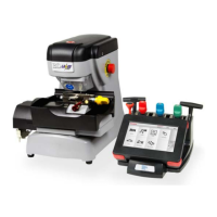
How to proceed:
• press slightly on the tongues of the fuse carrier to pull it
out from its seat;
•inspect the fuses;
• replace any damaged fuse with a new one of the same
capacity (Amperage) and type (slow);
• put back the fuse carrier into its seat.
9.2.8 Replacing the motor belt
Required tools
• 3mm hexagon wrench.
Safety warning
Before carrying out this operation disconnect the
power cable from the mains.
How to proceed:
• remove the top cover;
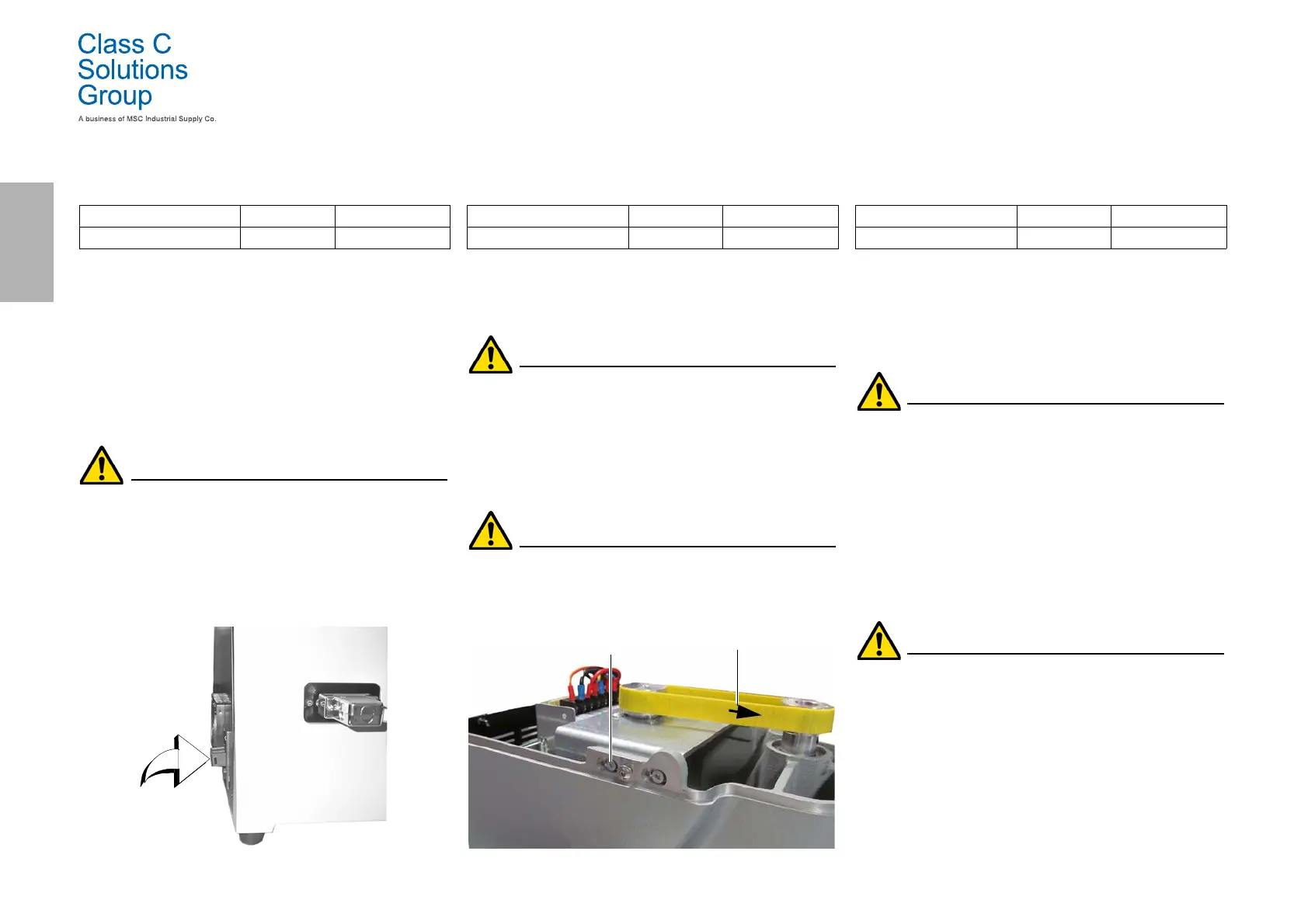
• use the 3mm hexagon wrench to loosen the 4 screws that
fasten the motor supporting unit;
• pull the motor supporting unit gently towards you to
reduce the belt tension;
• remove the belt from its seat and replace it with a new one.
When installing the belt again, make sure you respect
the direction marked by the arrow.
• put the motor supporting unit back into its initial position
and adjust the belt tension;
• fasten by tightening the 4 screws, put the back cover back
into its initial position and lock it.
9.2.9 Replacing the X axis sensor
Required tools
•2mm hexagon wrench.
• 13mm adjustable wrench.
Safety warning
Before carrying out this operation disconnect the
power cable from the mains.
How to proceed:
• remove the back cover and the protection grid of the card
and cut the straps;
• disconnect the cable from the electronic card;
• remove the bottom cover;
• use the adjustable wrench to loosen the nut that fastens
the sensor;
• unscrew and remove the sensor and replace it with a new
one;
• after fastening and locking the new sensor, move the
carriage towards it using the relevant controls.
IMPORTANT! Leave 0.02mm clearance between point A
and B.
• put back the bottom cover into its initial position and
fasten it;
• connect the cable of the new sensor to the electronic card;
• fix the cables with new straps;
• close the rear carter and the protection grid of the card and
fix them.
Spare part description Code Frequency
Rapid fuse 4A 5x20 RIC02592B When required
Spare part description Code Frequency
Belt 15X334-994 RIC03304B When required
Fastening screws
Arrow indicating direction
Spare part description Code Frequency
X axis sensor-994 RIC03306B When required