ENGLISH
Class C Solutions Group BD LASER MAX Man. cod. B409652FG 21
MAINTENANCE, DISMANTLING AND DISPOSAL
9.2.10 Replacing the Y axis sensor
Required tools
• 2mm hexagon wrench.
• 13mm adjustable wrench.
Safety warning
Before carrying out this operation disconnect the
power cable from the mains.
How to proceed:
• remove the jaw: first release it by rotating the knob that
locks it and then pull it out from its seat;
• remove the scrap material container;
• use the 2.5 mm wrench to remove the cover of jaw
assembly;
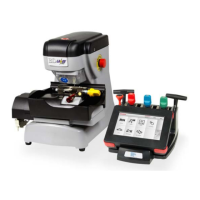
• take off the Y sensor cover by removing the 4 screws that
lock it;
• disconnect the sensor connector;
• use the adjustable wrench to loosen the nut that fastens
the sensor;
• unscrew and remove the sensor and replace it with a new
one;
• connect the connector;
• after fastening and locking the new sensor, move the
carriage towards it using the relevant controls.
IMPORTANT! Leave 0.02mm clearance between point A
and B.
• put back the cover, the scrap material container and the
jaw into their initial positions.
B
A
X sensor
Fastening
Carriage
Controls
to move
the carriage
nut
X sensor connection
Spare part description Code Frequency
Y axis sensor-994 RIC03412B When required
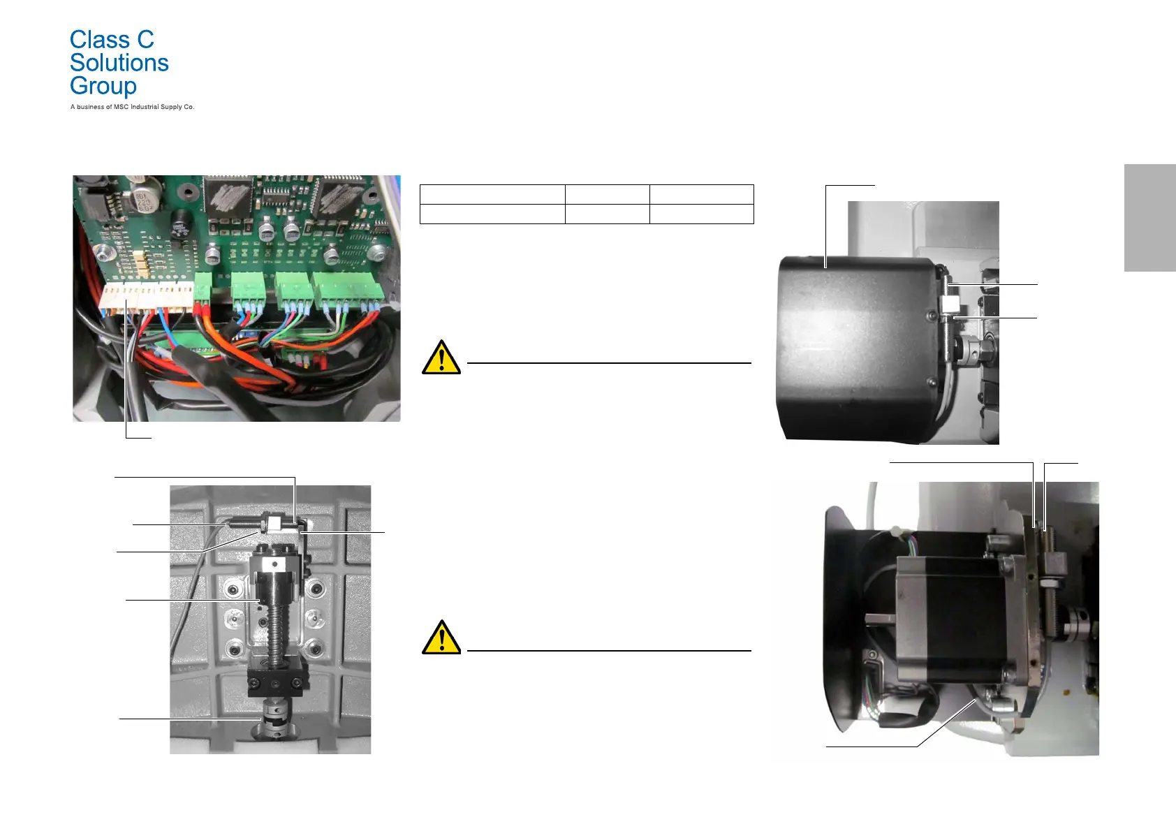
Y sensor
B
A
Y sensor
Y sensor cover
Fastening
nut
connector