78.7007.01
Ø 1/4’’
Ø 1/8’’
Ø 1/8’’
EAGLE ARTEK
MOUNTING TEMPLATE
1
4
b
a
2 3
0’
0’
15°
30°
45°
3’
3’
3’
6’
6’
6’
9’
9’
9’
0’
0’
0°
+30°
-30°
3’
3’
3’
6’
6’
6’
9’
9’
9’
7.2” 7.2”
75.0072.02 EAGLE ARTEK 20231023 Page 7 of 12
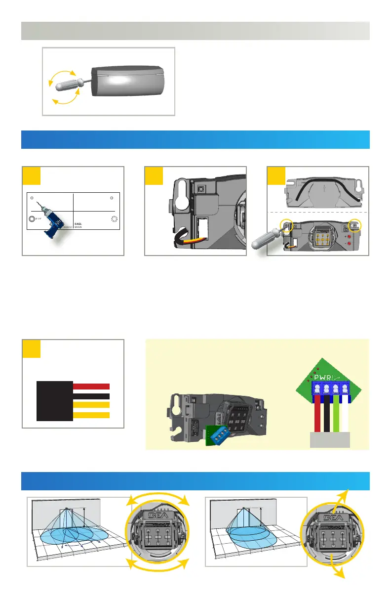
MOUNTING & WIRING
FIELD ANGLE ADJUSTMENTS
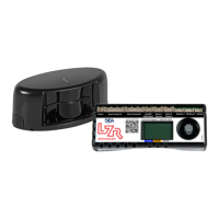
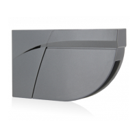
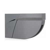
OPENING THE SENSOR
Insert the screwdriver on the left or
right notch of the sensor and twist to
remove the cover.
Using the mounting template,
drill the cable pass-thru hole
and 2 mounting holes.
Cable pass-thru: Ø 1/4“
Mounting holes: Ø 1/8“
Wire to the door controller.
Logic selectable via remote control
(see following page)
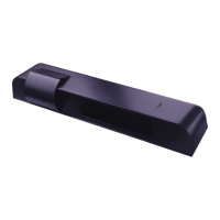
a) Route the cable relative to
the pass-thru hole. To avoid
damage, use the dedicated
cable path on the sensor base.
b) Secure the sensor by hand-
tightening the mounting
screws.
1 - RED - POWER SUPPLY
2 - BLACK - POWER SUPPLY
3 - YELLOW - ACTIVATION
4 - YELLOW - ACTIVATION
Pull the cable through the
pass-thru hole, and plug in
the connector accordingly.
RETROFITTING: OPTIONAL HARDWIRING
If you wish to utilize the existing cable from
the door control, simply install the Retrofit
Interface module (10EARETROFIT).
Adjust the lateral antenna angle.
Adjust the vertical antenna angle.
to
door control
red
white
black
green