Mounting and wiring
Real-time Ethernet port multiplier 27
Version: 2.6
3.4 LEDs and connection
The CU2508 has 4 diagnosis LEDs.
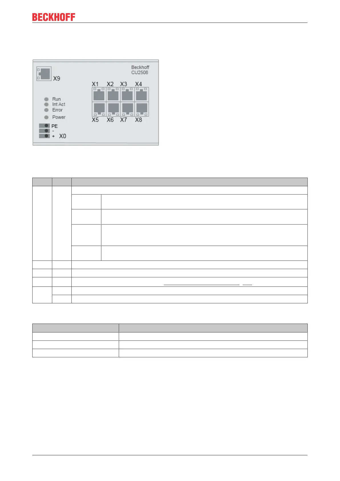
Fig.26: CU2508 front view
LEDs
LED Color Meaning
RUN green This LED indicates the operating state of the CU2508 running as an EtherCAT device
off State of the EtherCAT State Machine: INIT = initialization of the terminal or
BOOTSTRAP
flashing State of the EtherCAT State Machine: PREOP = function for mailbox
communication and different standard-settings set
single
flash
State of the EtherCAT State Machine: SAFEOP = verification of the sync
manager channels and the distributed clocks.
Outputs remain in safe state
on State of the EtherCAT State Machine: OP = normal operating state; mailbox and
process data communication is possible
Int Act green flashes when data traffic occurs
Power green on, when the device is powered correctly
Error yellow
an error has occurred (see chapter "Error handling and diagnosis [}25]")
X1 -
X8
green Link/Activity
yellow internal buffer overflow, alignment error detected
Pin assignment
Terminal point Comment
X0 24V
DC
power supply: +, GND and shield connection (functional earth)
X1..X8 DownLink Port FastEthernet 10/100Mbit
X9 UpLink Port Gbit Ethernet
Shielding concept
The PE/shield connection is connected to the metal housing. It should be used as functional earth to protect
from interference.