Product overview
EL9xxx 23Version: 3.9
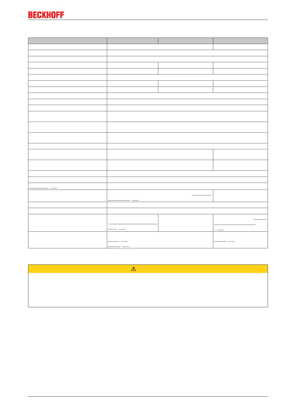
Technical data
Technical data EL9100 EL9110 EL9190
Nominal voltage 24 V DC variable, up to 230 V AC/DC
Power contact current load max. 10 A
Electrical isolation 500V (E-bus/field potential)
Current consumption from E-Bus - typ. 90 mA -
Bit width in the process image - 1 bit (diagnosis) -
Configuration no address or configuration settings
Power LED yes yes no
Diagnosis no yes, in process image no
Electrical connection to mounting rail no
PE contact yes
Renewed infeed yes
Connection facility to additional power con-
tact
1
Side by side mounting on Bus Terminals
with power contact
yes
Side by side mounting on Bus Terminals
without power contact
yes
Weight approx. 50 g
Permissible ambient temperature range
(during operation)
-25°C ... +60°C (extended temperature range) 0°C ... +55°C
Permissible ambient temperature range
(during storage)
-40°C ... +85°C -25°C ... +85°C
Permissible relative humidity 95%, no condensation
Dimensions (W x H x D) approx. 15 mm x 100 mm x 70 mm (width aligned: 12 mm)
Mounting [}73]
on 35 mm mounting rail conforms to EN 60715
Vibration/shock resistance
conforms to EN60068-2-6/EN60068-2-27, see Installation
instructions [}76] for enhanced mechanical load capacity
conforms to EN 60068-2-6/
EN 60068-2-27
EMC resistance burst/ESD conforms to EN 61000-6-2/EN 61000-6-4
Protect. class IP 20
Installation pos. variable, see chapter
"Mounting of Passive Termi-
nals [}83]"
variable
variable, see chapter "Mount-
ing of Passive Terminals
[}83]"
Approval CE
ATEX [}85]
cULus [}86]
CE
cULus [}86]
Connection EL9100, EL9110, EL9190
CAUTION
Hazard to individuals and devices!
When designing a Bus Terminal block with different potentials on the power contacts (e.g. 230 V AC/DC
and 24 V DC), please note that it is mandatory to use potential separation terminals (EL9080)!
Bring the bus system into a safe, powered down state before starting installation, disassembly or wiring of
the Bus Terminals!
 Loading...


