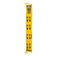
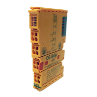
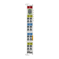
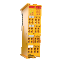
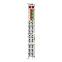
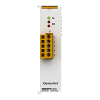
Product overview
EL9xxx 63Version: 3.9
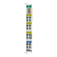
Terminal point Meaning
Indication No.
R
external
1 Connection for ballast resistor
+U
IN
2 Positive input for buffer voltage (internally connected with
terminal point 3 and 4)
+U
IN
3 Positive input for buffer voltage (internally connected with
terminal point 2 and 4)
+U
IN
4 Positive input for buffer voltage (internally connected with
terminal point 2 and 3)
R
external
5 Connection for ballast resistor
-U
IN
6 Negative input for buffer voltage (internally connected with
terminal point 7 and 8)
-U
IN
7 Negative input for buffer voltage (internally connected with
terminal point 6 and 8)
-U
IN
8 Negative input for buffer voltage (internally connected with
terminal point 6 and 7)
3.13.2 Application example
WARNING
Risk of electric shock and damage of device!
Bring the bus terminal system into a safe, powered down state before starting installation, disassembly or
wiring of the Bus Terminals!
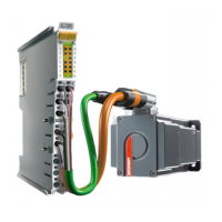
Application example
• The capacitor within the EL9570 compensates peaks on the power supply of the stepper motor / DC
motor.
• As soon as the supply voltages increases 55 V, the EL9570 switches on the brake resistor R
EXTERNAL
, to
burn the back loaded braking energy of the stepper motor / DC motor connected to the EL7041.
 Loading...
