Product overview
EL9xxx 43Version: 3.9
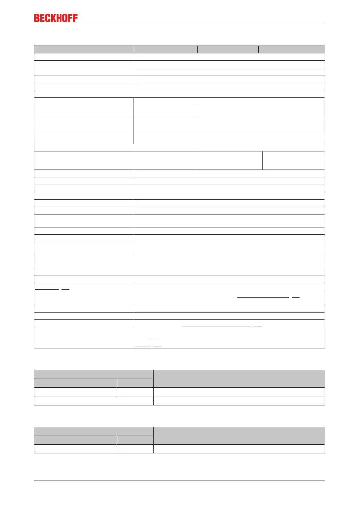
Technical Data
Technical Data EL9184 EL9188 EL9189
Nominal voltage ≤ 60 V
DC
Current load ≤ 10 A
Power LED -
Error LED -
Message to E-Bus -
Shield connection -
Renewed power feed -
Connection facility to additional power con-
tact
8 16
Side by side mounting on EtherCAT Termi-
nals with power contact
yes, left side without PE
Side by side mounting on EtherCAT Termi-
nals without power contact
-
PE contact no
Outputs 2 x 8
(e.g.: 8 x 24 V contact, 8 x 0
V contact)
16
(e.g. 16 x 24 V contact)
16
(e.g. 16 x 0 V contact )
Current consumption from E-Bus -
Bit width in the process image 0
Electrical connection to mounting rail -
Electrical isolation 500 V (E-bus/field potential)
Configuration no address or configuration settings
Conductor types solid wire, stranded wire and ferrule
Conductor connection solid wire conductors: direct plug-in technique; stranded wire conductors and ferrules:
spring actuation by screwdriver
Rated cross-section solid wire: 0.08…1.5 mm²; stranded wire: 0.25…1.5 mm²; ferrule: 0.14…0.75 mm²
Weight approx.. 60 g
Permissible ambient temperature range (dur-
ing operation)
-25°C ... +60°C (extended temperature range)
Permissible ambient temperature range (dur-
ing storage)
-40°C ... +85°C
Permissible relative humidity 95%, no condensation
Dimensions (W x H x D) approx. 15 mm x 100 mm x 70 mm (width aligned: 12 mm)
Mounting [}73]
on 35 mm mounting rail conforms to EN 60715
Vibration/shock resistance
conforms to EN60068-2-6/EN60068-2-27, see Installation instructions [}76] for en-
hanced mechanical load capacity
EMC resistance burst/ESD conforms to EN 61000-6-2/EN 61000-6-4
Protect. class IP 20
Installation pos.
variable, see chapter "Mounting of Passive Terminals [}83]"
Approval CE
ATEX [}85]
cULus [}86]
Connection EL9184
Terminal point Description
Indication No.
+24 V 1 - 8 +24 V output (internally connected with positive power contact)
0 V 9 - 16 0 V (internally connected with negative power contact)
Connection EL9188
Terminal point Description
Indication No.
+24 V 1 - 16 +24 V output (internally connected with positive power contact)
 Loading...


