16 17Quick Start Guide1273
Connecting up
The 1273 unit uses the following leads and connectors:
Analog Inputs:
Mic/Line Input - Transformer Balanced XLR and ¼" TRS connectors
- 300/1200 Ω Mic, 10 kΩ Line
- Instrument input 600 kΩ
Analog Outputs:
Line Output - Transformer Balanced XLR and ¼" TRS connectors - <80 Ω
Power Connections:
IEC mains inlet – 100-240 V AC~50-60 Hz
For further information about the connectors used in conjunction with the 1273 unit, see Section 5. Connectors.
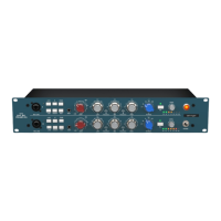
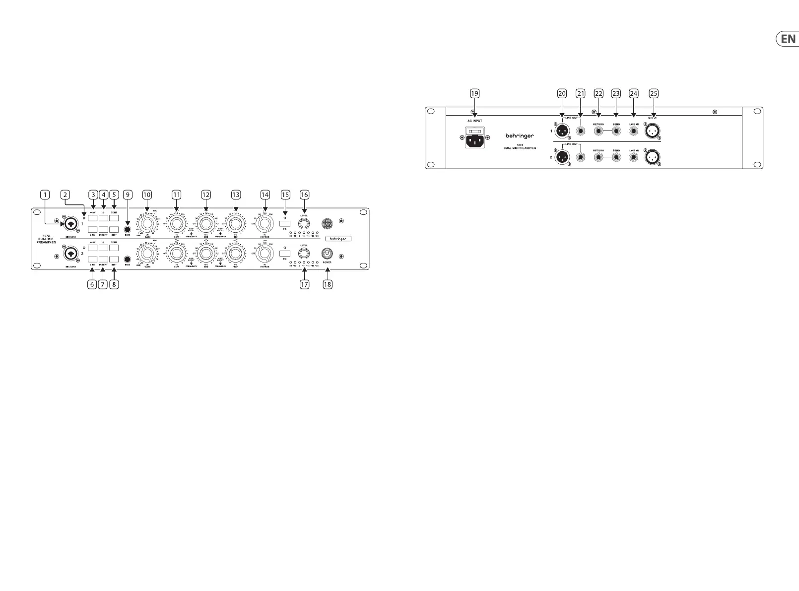
3. Front Panel
1. Mic/Line input – Combo jack provides balanced female XLR and ¼" TRS input connections for mic/line equipment.
Unbalancedsignals can also be connected by using ¼" TS connectors with the ¼" chassis connectors.
2. +48 V LED – Indicates if +48 V phantom power is active.
3. +48 V – Push to apply +48 V phantom power to the front and rear XLR inputs
4. Ø – Polarity 180° invert button.
5. TONE – This changes the input impedance for the mic input, button out is 1200 Ω, pushed in is 300 Ω.
6. LINE – Selects the line input to be used. This button disables the other 2 inputs (Mic/Inst).
7. INSERT – The Insert point is post gain, pre-EQ and could be used to add a compressor pre-EQ.
8. INST – Activates the front panel instrument input. This button disables the other 2 inputs (Mic/Line). The input transformer is also in
the instrument path, therefore when the tone button is used there will be a slight warming eect.
9. INST Input - Unbalanced signals can also be connected using ¼" TS connectors with the ¼" chassis connectors.
10. GAIN – The preamp has a gain range of -20 dB to 80 dB in 5 dB steps.
11. LOW – The low band has ±15 dB gain adjusted with the outer control. The inner control selects the frequency: o, 35 Hz to
220 Hz in 5 steps.
12. MID – The mid band has ±15 dB gain adjusted with the outer control. The inner control selects the frequency: o, 360 Hz to
7.2 kHz in 7 steps.
13. HIGH – The high band has ±15 dB gain adjusted with the outer control. The inner control selects the frequency: o, 10 kHz to 16 kHz
in 4 steps.
14. HI PASS – Control for the high pass lter can be set to: O, 50 Hz, 80 Hz, 160 Hz and 300 Hz.
15. EQ IN – Switch the EQ in and out of circuit. The LED indicates the EQ circuit is active.
16. OUTPUT LEVEL - To achieve the full gain as indicated on the gain switch, level has to be set to full (0 dBu in, 0 dBu out for 0 dB on
gain switch setting).
17. METER – Shows output level from -30 dB to 24 dB.
18. POWER – Turn the unit on and o. Up is ON.
4. Rear Panel
19. POWER – Mains IEC socket.
20. LINE OUT XLR – Balanced male XLR.
21. LINE OUT TRS – ¼" TRS output connections for line equipment. Unbalanced signals can also be connected using ¼" TS connectors
with the ¼" chassis connectors.
22. RETURN – Insert return using ¼" TS input connections for line level equipment.
23. SEND – Insert send using ¼" TS output connections for line level equipment.
24. LINE IN – Line input using ¼" TRS input connections for line level equipment.
25. MIC IN – XLR input for microphones.