GB Sound module MSM-1
27 BEIER-Electronic 18.01.2024
Connection of switching outputs 1 - 8:
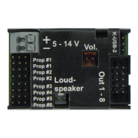
The outputs 1 - 8 of the module are on the pin connector X3.
The supplied ribbon cable one can be used to connect the outputs. For easier
connection, we also offer connection terminal clamps AKL-8 and AKL-8-W in our
shop.
Of course, other cables/plugs can also be connected to the pins of X3. A cable cross
section of 0.14 mm² - 0.5 mm² should be used for the switching outputs.
The sound module always switches the negative pole to the connected load for all
outputs. The negative pole of the load is connected to the output of the sound
module (see connection diagram).
The common positive pole for outputs 1 – 8 are the black and white wires. It is also
possible to connect the load directly to the positive terminal of the battery.
Assignment of the ribbon cable:
The voltage on the positive pins of X3 is as high as the module's supply voltage.
If LEDs are connected, series resistors must always be used. It doesn't matter
whether the series resistors are connected to the plus or minus line.
The correct polarity is important for LEDs, otherwise they will not light up.