GB Sound module MSM-1
29 BEIER-Electronic 18.01.2024
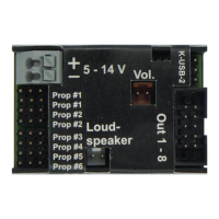
Connection of the proportional inputs
Up to 6 proportional channels of an RC receiver can be connected to the pins X2/1 –
X2/6. The 6 supplied servo patch cables are used for the connection.
The 6 proportional inputs are marked on the cover of the sound module. Prop #1 and
#2 are each designed twice so that the proportional signal can be passed on to the
speed controller or steering servo.
The servo patch cables are plugged onto the sound module so that the brown cable
points to the edge of the board and the orange cable points to the center of the
board.
Prop #1 (X2/1) is always the gas channel. A connection to the gas channel of the
receiver must be established here. The servo cable of the speed controller is plugged
into the 2nd connection of Prop #1.
Prop #2 (X2/2) is the steering channel on most model types. The first connection of
Prop #2 is connected to the steering channel of the receiver. The steering servo
plugs into the 2nd port of Prop #2.
The channel numbers of the sound module (Prop #1 - #6 are not related to the
channel numbers of the receiver. Channel #1 of the receiver does not necessarily
have to be connected to Prop #1 of the sound module. If the control stick for
accelerating, for example on the receiver, is on channel #3, then channel #3 of the
receiver is connected to prop #1 of the sound module.
The neutral positions of Prop #1 and Prop #2 are re-read from the receiver every
time the MSM-1 is switched on. It is important to ensure that the throttle and steering
are in neutral position when the model is switched on or the battery is plugged in.
The neutral positions of Prop #3 – Prop #6 are fixed at 1,500 ms. This is the standard
value for current remote controls.
If the speed controller has a BEC (a power supply for the receiver), the BEC voltage
is forwarded from the speed controller to the receiver via connectors X2/1 or X2/2.