20
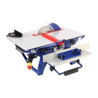
the thickness less than 60 mm. It is shipped dismounted. The kit of parts (Table 2) is packed
in a separate box. The assembly of the holding down device is performed as shown in the
Figure J. To fix the holding device, use screws 23 and 8-mm washers.
Fig. J
Holding down device
74 – spring box, 75 – right support, 76 – left support, 77 – rotating axis, 78 – clamp axis, 79 – clamp handle,
80 – screw nut М8, 81 – washer spring
10.2 Setting up the machine
Install the machine on a freely accessible, sturdy, level surface. It is useful to additionally
scerw the machine with the help of mounting bolts (not included in the scope of delivery).
The holes in the bearing surface of the machine feet serve for mounting.
Check the intactness of the basic parts; fastening security of the separate parts; bolts, screws
and nuts tightening; locking; integrity of the supply cord, plug and socket; availability of the
safety fencing.
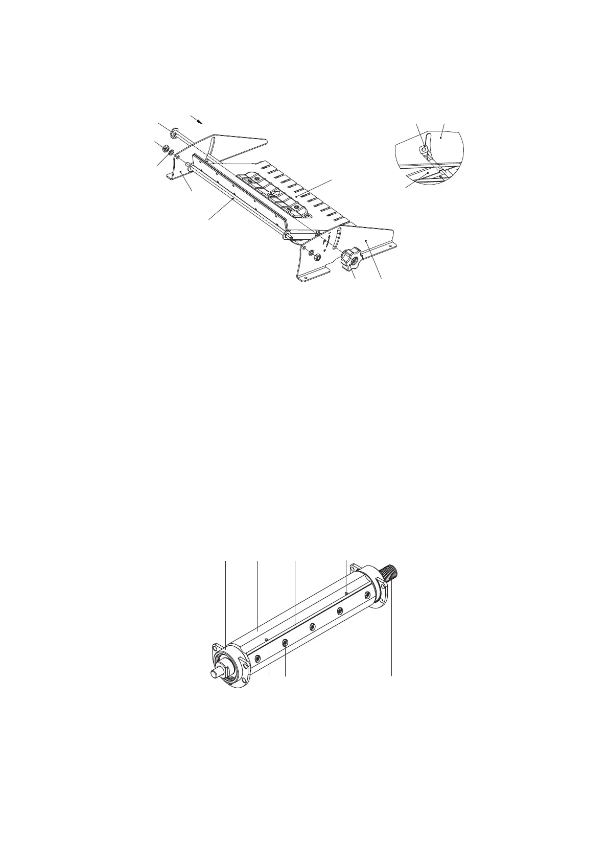
10.3 Installing and adjusting the knives
The knife adjustment is performed by consistent installation of each blade. It is necessary to
loosen the knife 70 by removing five screws 71 in advance. (Fig. K).
Fig. K
The cutter block construction
1 – cutter block; 1а – block casing; 1b – end shields; 69 – knife holder; 70 – slicing blade;71 – fixing screw for the
knife holder; 72 – adjusting device
74
74
78
78
80
81
76
76
77
79
75
69 71
70 72
1
1a1b