23
11.1.1 Installing the planning table
The loading 2 and outfeed 3 tables should be installed at the level of the slicing blade cut (Fig. O).
To get that done:
loose the flywheels 6;
pull the locking clip 52 (horizontally) by holding it from the bottom, and lower the tables
by moving the lever-sticks 4 and 5 down against stop;
the bracket 8 with fencing 7 should be mounted on the plane of the outfeed planing table
3 and fixed with the help of the flywheel 19.
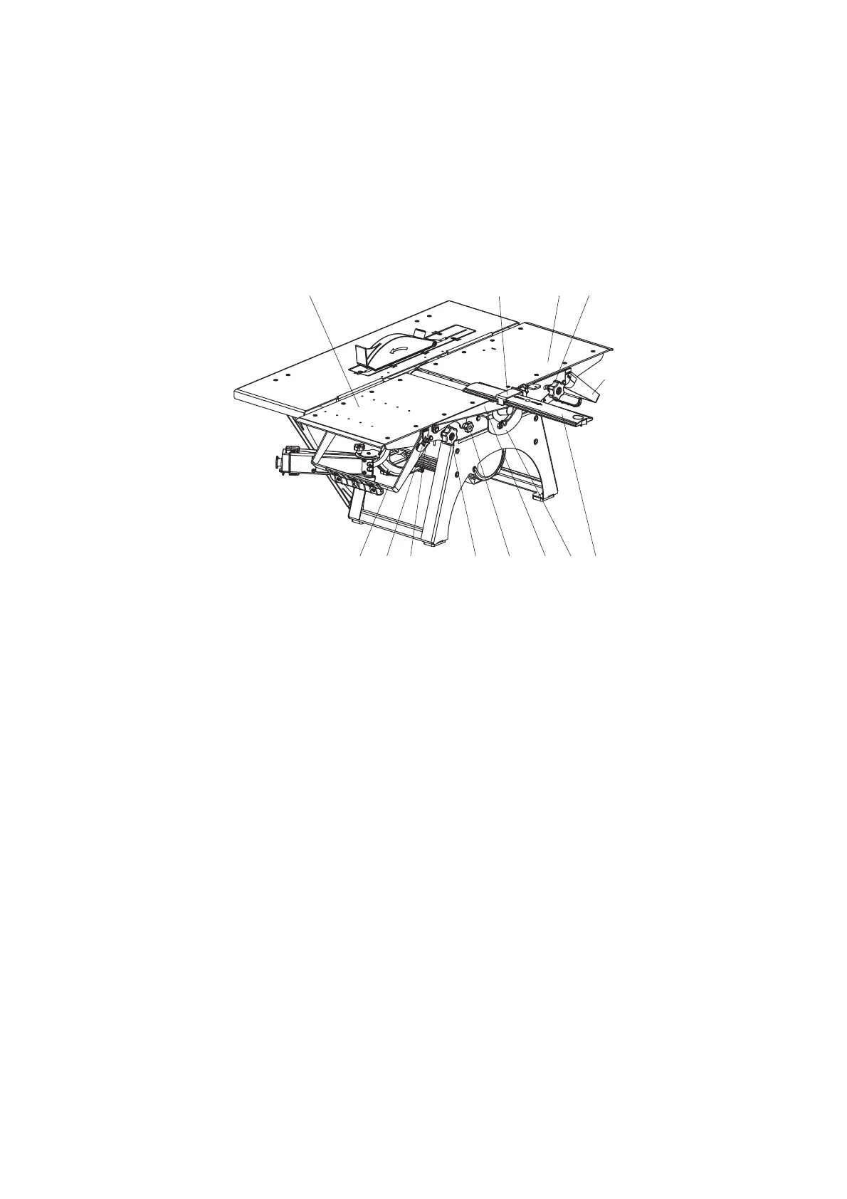
Fig. O
Installing planning tables
2 – loading table; 3 – outfeed table; 4 – lever-stick of the loading table; 5 – lever-stick of the outfeed table;
6 – flywheels for loading and outfeed table fixation;7 – knife’s block fencing; 8 – swinging bracket; 9 – fixation clip;
14 – scale, 14а – survey-line of the planning depth; 19 – flywheel for bracket fixation; 52 – locking clip.
11.1.2 Adjusting the planing depth
To adjust the planning depth, perform the following (Fig. O):
unscrew the flywheel 6 of the loading table 2;
move the table to the desired planing depth (0÷3 mm) by moving up/down the lever-stick
4, aligning the survey-line 14a on the loading table with the appropriate value on the scale
14;
fix the loading table 2 in this position by tightening the flywheels 6 of the loading table.
11.1.3 Adjusting the fencing
The fencing 7 is designed to close those parts of the rotating cutter block which are not
located in the cutting area (inactive parts of the knife (cutter) block) while the machine is
running. (Fig. P).
While half-width planning, the fencing 7 should be moved to the required planning width.
To move the fencing 7 into the necessary position it is required:
to loosen the flywheel;
to move the fencing 7 along the cutter block in the direction of arrows 7а;
to tighten the flywheel.
7819 5214a14 6
9362
4
5