Instruction Manual for DAC3 HGC and DAC3 L with 2.X Firmware Page 55
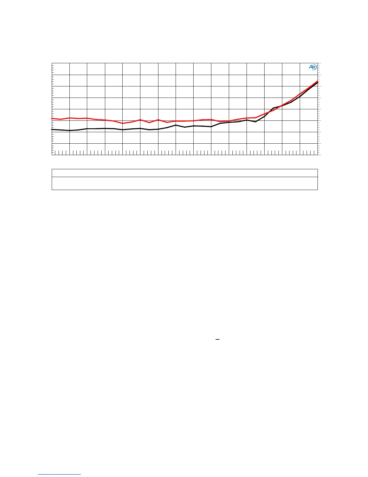
Graph 9 - THD vs. Amplitude - Balanced vs. Unbalanced Outputs
This plot demonstrates that the balanced and unbalanced analog outputs on the DAC3 have very
similar THD performance. The unbalanced outputs (red curve) closely match the performance of
the balanced outputs (black curve) at high signal levels. The separation between the curves at
signal levels below -10 dBFS is due to the improved SNR provided by the balanced interfaces. At 0
dBFS, the balanced interfaces were calibrated to +24 dBu (12.28 Vrms) while the unbalanced
interfaces were calibrated to +8.24 dBu (2 Vrms). The higher signal levels used with the balanced
interfaces make it easier to achieve high signal to noise ratios. This is just one reason why
Benchmark recommends balanced interconnects.
The DAC3 includes differential amplifiers that remove common-mode THD from the balanced
outputs of the SABRE-PRO converters. These differential amplifiers give the unbalanced outputs the
ability to approach the THD performance of the balanced outputs. Please note that the differential
amplifiers also eliminate common-mode distortion on the balanced outputs.
Top-quality D/A conversion chips (such as the ES9028PRO) are equipped with balanced outputs.
These balanced outputs allow a significant reduction of THD if they are followed by precision
differential amplifiers. Conversion chips tend to produce significant common-mode distortion
products that should be removed by a differential amplifier. The DAC3 includes precision
differential amplifiers following the outputs of the ES9028PRO. Many competing products omit
these differential amplifiers. The omission of the differential amplifiers would make the THD much
higher on the unbalanced outputs. The differential amplifiers also improve the system performance
when the balanced outputs are driving balanced inputs that are not precisely trimmed.
The THD measurements shown above confirm the effectiveness of the differential amplifiers in the
DAC3. Additional confirmation can be obtained by measuring the THD of either side of the
balanced outputs relative to ground.
DAC3 - THD vs. Amplitude, 1 kHz, 0 dBFS = 2Vrms
Balanced vs. Unbalanced Outputs
DAC3 - THD vs Amplitude Balanced vs Unbalanced.at27
ColorSweep
Trace Line Style Thick
Data Axis Comment Source 2
1
3 Black
Solid 4 Distortion.Ch.1 Harm Sum1 Right THD Balanced Output : 2.00000 =Swr.Ch. A Input
2
2 Red Solid 4 Distortion.Ch.1 Harm Sum1 Left THD Unbalanced Output
: 4.00000 =Swr.Ch. A Input
-140
-100
-135
-130
-125
-120
-115
-110
-105
-140
-100
-135
-130
-125
-120
-115
-110
-105
-30
-0
-28 -26
-24
-22 -20 -18 -16 -14 -12 -10 -8 -6 -4
-2