Instruction Manual for DAC3 HGC and DAC3 L with 2.X Firmware Page 61
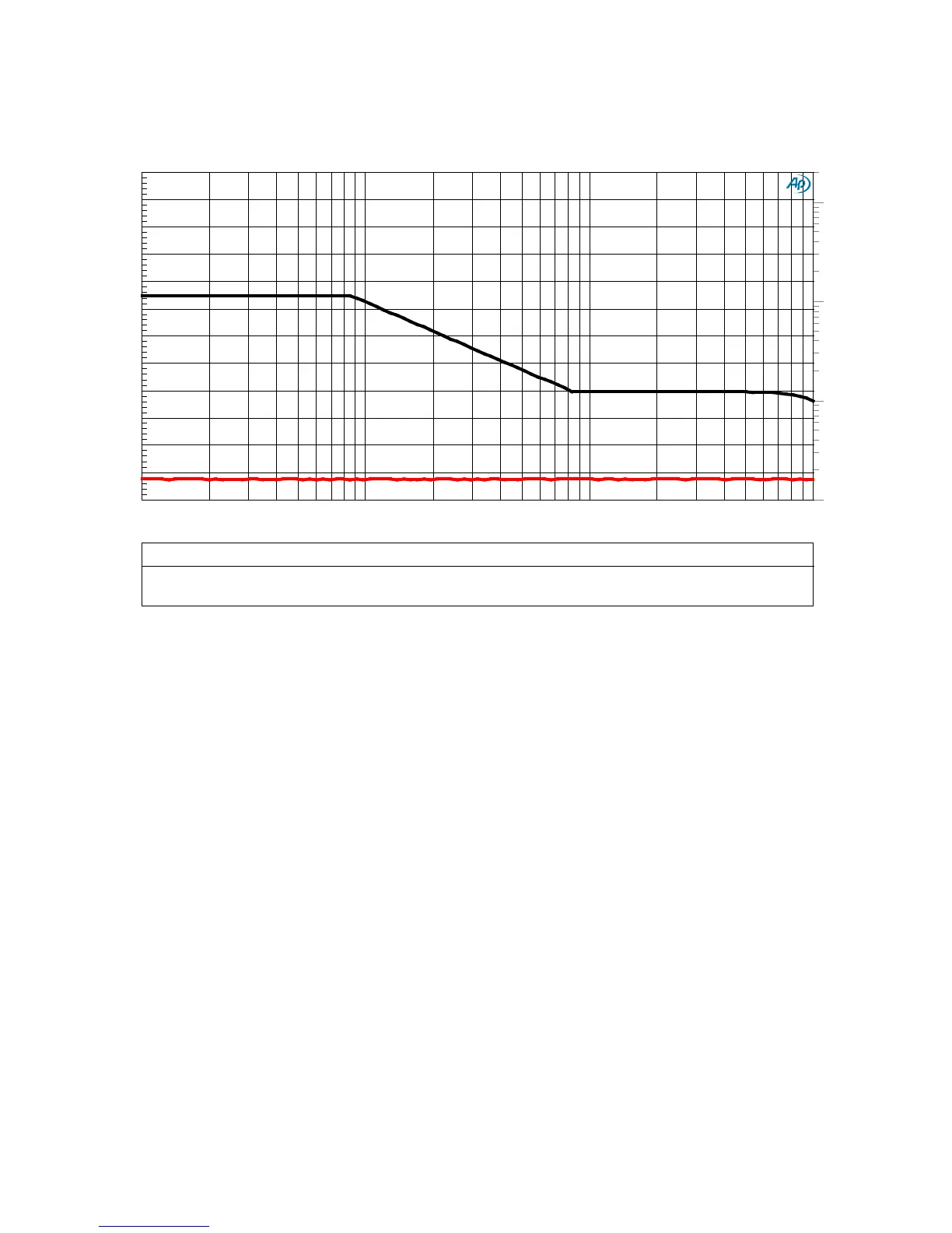
Graph 15 - Jitter Tolerance
The Audio Engineering Society (AES) has created a jitter tolerance template for testing digital audio
devices. The black curve shows the AES jitter tolerance template (see right-hand vertical axis).
Induced jitter approaches 5 UI at 200 Hz, and is reduced to 0.125 UI above 8 kHz. The red trace
shows the THD+N of the DAC3 (left-hand vertical axis) while being driven with the jitter shown on
the black curve. Over the entire range of the AES jitter tolerance test, the THD+N performance of
the DAC3 is unchanged. The DAC3 easily passes the AES jitter tolerance test, and it does so
without any performance degradation.
DAC3 - INTERFACE JITTER TOLERANCE - Distortion vs Jitter
3.456 kHz Test Tone at 0 dBFS, THD+N 22 to 22 kHz BW
DAC3 - JITTER TOLERANCE.at27
ColorSweep Trace Line Style Thick Data Axis Comment
1 1 Red Solid 4 Anlr.THD+N Ratio Left
1 2 Black Solid 4 Dio.Interface Jitter Right
10m
20
20m
50m
100m
200m
500m
1
2
5
10
-120
+0
-110
-100
-90
-80
-70
-60
-50
-40
-30
-20
-10
100 90k 200 500 1k 2k 5k 10k 20k 50k