3
TBP201007fren / 04.2011
A-ISOMETER® IR427 plus MK7
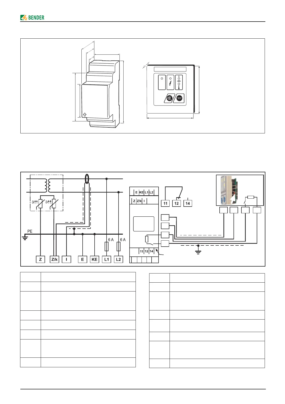
Dimensions
Wiring diagram
Connect the device according to the wiring diagram.
The leads to KE and E have to be run separately!
Terminal Connections
E, KE Separate connection of E and KE to PE
L1, L2
Connection to the IT system to be monitored;
supply voltage U
S
(see nameplate) 6 A fuse recom-
mended.
Z, Z/k Connection to temperature sensors (PTC)
Z/k, l
Connection to the measuring current transformer
(STW2)
1, 2
U
S
for alarm indicator and test combination MK7
3, 4
RS-485 interface;
Terminate the connection with switch R (on, off) if
the device is connected at the end of the bus
11, 12, 14 Alarm relay K1
Dimensions
Schéma de branchement
Connectez l´appareil selon le schéma de branchement.
Les branchements sur KE et E doivent être effectués séparément !
Borne Raccordements
E, KE Connexion séparée de E et KE au PE
L1, L2
Raccord au réseau IT à surveiller;
Tension d´alimentation U
S
(cf. plaque signalétique)
via un fusible 6 A
Z, Z/k Raccord à la sonde de température(PTC)
Z/k, l Raccord au tore de détection (STW2)
1, 2
U
s
pour système de report d´alarme MK7
3, 4
Interface RS-485,
Terminer le raccord avec l´interrupteur R (on/off), si
l´appareil est connecté en fin de bus
11, 12, 14 Relais d´alarme K1
90 mm
45
67,5
36 mm
31,1
47,5
70,5
80 mm
80
10
ON
MK7
on
off
1
234
1
2
24 V
0 V
3
4
34
12
RS485
on
off
R
L
N
J-Y(St)Y 2x2x0,6
IR427
STW2
R