2 isoRW425_D00052_04_Q_XXEN / 03.2019
ISOMETER® isoRW425
i
Information!
Read the corresponding manual in addition to this quickstart.
Downloadable at: www.bender.de/en/service-support/downloads
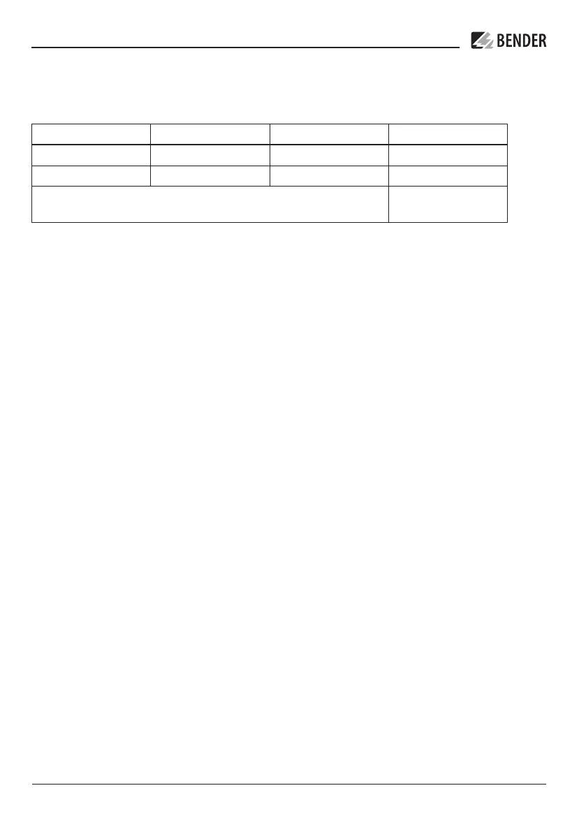
Type of device Version Manual No. Art. No.
isoRW425-D4W-4 Push-wire terminal D00052 B71037000W
isoRW425-D4W-4 Screw-type terminal D00052 B91037000W
Mounting clip for screw fixing
(1 piece per device)
B98060008
Intended use
The ISOMETER® monitors the insulation resistance R
F
(R mode) or the insulation impedance Z
F
(Z mode) of unearthed AC/DC main circuits (IT systems) with nominal system voltages of
3(N)AC, AC, AC/DC or DC 0 … 440 V. DC components existing in 3(N)AC, AC/DC systems do not in-
fluence the operating characteristics, when a minimum load current of DC 10 mA flows.
A separate supply voltage U
s
allows deenergised systems to be monitored as well. The maximum
permissible system leakage capacitance C
e
is 300 μF in R mode and 1μF in Z mode.
Any use other than that described in this quickstart is regarded as improper.
i
To ensure that the ISOMETER® functions correctly, an internal resistance of ≤ 1 kΩ must exist
between L1/+ and L2/- via the source (e.g. the transformer) or the load.