isoRW425_D00052_04_Q_XXEN / 03.2019 5
ISOMETER® isoRW425
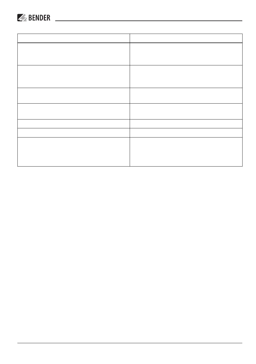
Wiring diagram legend
Terminal Connections
A1, A2 Connection to the supply voltage U
s
via a fuse:
If supplied from an IT system, both lines have
to be protected by a fuse.*
E, E, KE Connect each terminal separately to PE:
The same wire cross section as for „A1“, „A2“ is
to be used.
L1/+, L2/– Connection to the 3(N)AC, AC or DC system to
be monitored
T/R Connection for external combined test and re-
set button
11, 14 Connection to alarm relay „K1“
11, 24 Connection to alarm relay „K2“
A, B RS-485 communication interface with selecta-
ble terminating resistance
Example: Connection of a BMS-Ethernet-
Gateway COM465IP
i
* For UL applications:
Only use 60/75°C copper lines!
For UL and CSA applications, it is mandatory to use 5 A fuses for the protection of the supply
voltage U
s
.
 Loading...


