isoRW425_D00052_04_Q_XXEN / 03.2019 7
ISOMETER® isoRW425
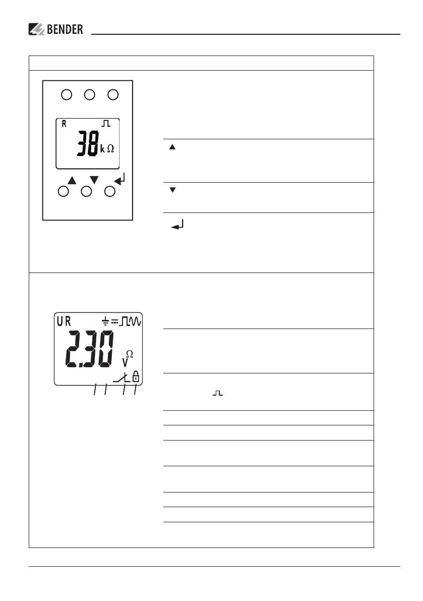
Display elements
Device front/display Function
ON AL1 AL2
TRMENU
ON
AL1
AL2
green - On
yellow - alarm
yellow - alarm
T
Up button
Test button (press > 1.5 s)
R
Down button
Reset button (press > 1.5 s)
MENU
ENTER
MENU button (press > 1.5 s)
+
test onoff MAdr
L1L2
C
<
>
s
kM %
Fµ
{
{
{
{
1
2
3
1 U: Nominal system voltage U
n
R: InsuIation resistance R
F
C: System leakage capacitance C
e
2 Monitored conductor
3 = : Voltage type DC
: Disturbance-free measurment value update
~ : Voltage type AC
4 Measured values and units
5 Password protection is activated.
6 In menu mode, the operating mode of the
respective alarm relay is displayed.
7 Communication interface
With measured value: isoData operation
8 The fault memory is activated.
9 Condition symbols
10 Identification for response values and response value
violation