Installation and connection
15
RCMA421H_D00069_00_M_XXEN/05.2014
1. Mounting on a DIN rail:
Snap the mounting clip at the rear of the device onto the DIN rail so
that it sits securely.
Screw fixing:
Using the tool, position the rear mounting clips (a second mounting
clip is required, see the ordering information) so that it protrudes over
the enclosure. Fix the device in place with two M4 screws.
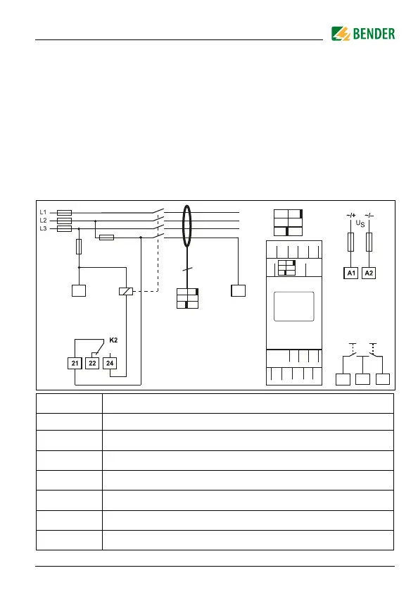
2. Wiring
The device must be wired as illustrated in the wiring diagram (exam-
ple).
Terminal Connections
A1, A2 Connection to the power supply
1 Bush for measuring current transformer's connecting cable
T1, T2 Test connections for internal monitoring circuit
T, T/R, R Connections for external test and reset button
21, 22, 24 Alarm relay K2: Connection to contactor or load switch
WN-…BS Measuring current transformers
K1 Recommended contactors are listed in the table on page 31
T1 T2
K1
K1
T1
A2A1
T2
1
21 2422
WN-...BS
6
<
U
k1
k2
T
I1
I2
T
3,15 A
3,15 A
T
T/R R
T T/R R