5. Operation and configuration
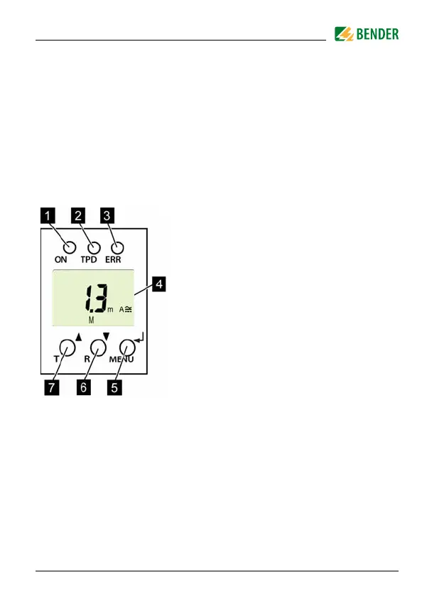
1 Green Power ON LED:
Lights up when the power supply voltage
is connected and the device is running.
2 Red TPD alarm LED:
Lights up when the rated residual operat-
ing current I
Δn
is exceeded.
3 Yellow ERR alarm LED:
Flashes in the event of system errors. An
error code will appear on the display, e.g.
E.03
4DISPLAY:
Displays operating information.
5 ENTER (< 1.5 s) / MENU (> 1.5 s) button:
Press this button to apply entries and
changes and call up the menu.
6 DOWN (< 1.5 s) / RESET (> 1.5 s) button:
Press this button to reduce input values
and navigate through the menu, as well
as to perform a reset.
7 UP (< 1.5 s) / TEST (> 1.5 s) button:
Press this button to increase input values
and navigate through the menu, as well
as to run a manual self test.
Fig. 5.1: User interface