HD-14T Four Post Lift 8 P/N 5900037 — Rev. F — February 2022
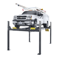
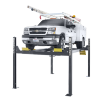
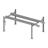
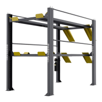
The main components of your HD-14T Lift include:
• Power Post. The Post that holds the Power Unit.
The Power Post can be in either of two
locations
. You can tell the Power Post from the other Posts because it has two Mounting
Brackets on it. Mount the Power Unit on one of the two Mounting Brackets.
• The other three Posts. These Posts are interchangeable.
• Power Unit. An electric/hydraulic unit that connects to an electric power source and then
provides Hydraulic Fluid to the Hydraulic Cylinder that raises and lowers the Runways.
• Powerside Runway. On the same side as the Power Post. The Powerside Runway has the
Hydraulic Cylinder and the Lifting Cables under them. The Powerside Runway
must
go next to the
Power Post.
• Offside Runway. The other Runway. It does not have a Hydraulic Cylinder or Lifting Cables
underneath it.
• Flex Tube. Not shown. A flexible, black tube that attaches to an opening on the Powerside
Runway on one end and to the bottom of the Flex Tube Bracket Plate (near the Power Unit) on the
other end. Used for routing the Air Line, Return Line, and Hydraulic Hose to the Power Unit.
• Utility Rails. Hold the optional Rolling Jacks. Utility Rails
must
face the inside of the Lift.
• Crosstubes. One at each end of the Lift. The Crosstubes are hollow; the Lifting Cables that raise
and lower the Runways are routed through the Crosstubes. The Crosstubes are not
interchangeable; each Crosstube has an opening (called a ‘Window’) that faces the inside of the
Lift.
Make sure to install the Lift so that the
Windows open to the inside of the Lift
only
.
• Drive-up Ramps. One for each Runway. Use them to drive onto and off of the Runways.
• Tire Stops. Located at the Front of the Lift, Tire Stops prevent the Vehicle’s Front Tires from
going any further forward. Additionally, we strongly recommend chocking the Vehicle’s Rear Tires.
• Safety Locks. Once engaged, they hold the Runways in position, even if the power goes out or
there is a leak in the Hydraulic Hoses.
Only leave the Runways on the ground or
engaged on a Safety Lock.
• Pushbutton Air Valve. Includes a Pushbutton that moves the Safety Locks away from the
Ladder so that they do not engage as you lower the Runways. Used only to lower the Runways.
Located next to the Power Post.
• Safety Ladders. Part of the Safety Lock System installed at the back of the Post, somewhat
resembles a Ladder.