11
Fig 3.7
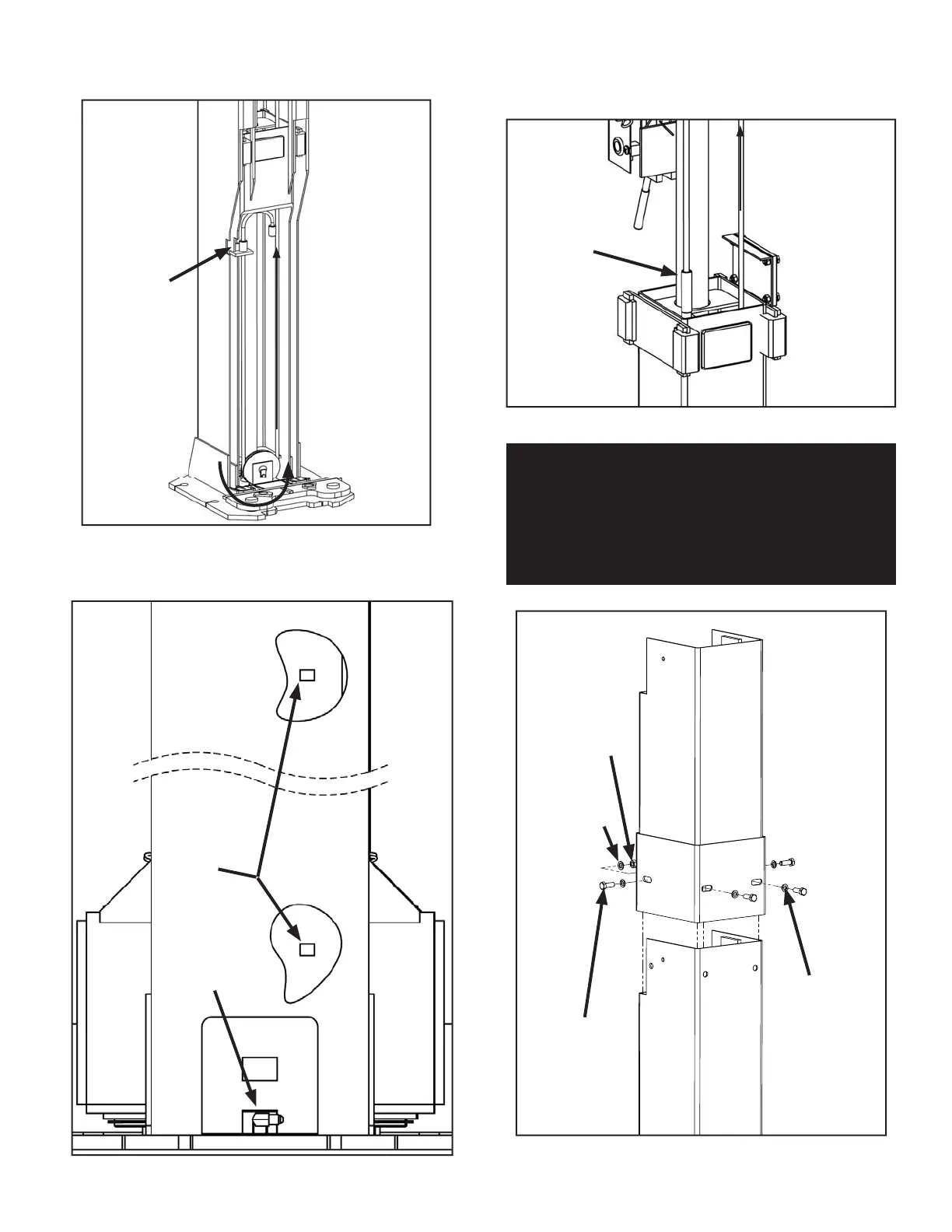
Fig 3.8
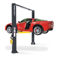
Fig 3.6
Threaded end of
cable routed up
through carriage
towards Over-
head Assembly
For Narrow
con guration,
lock cable
button into rst
button position
into Lock Plate
inside of car-
riage
NOTE: Portions of Carriage and Post cut away for clarity
NOTE: Second Cable Button should be tucked away from
the lifting cable route. Second Cable Button in Fig 3.5
shown for representational purposes only.
NOTE: Post hidden for clarity
Threaded
cable end from
other side of lift.
(Short cable on
assymmetric
models)
Power Side
Post depicted
Cable routed up
and across Over-
head Assembly to
opposite carriage.
(Long cable on
asymmetric models)
Fitting must be
turned towards
hose clips for
hydraulic hose
routing
NOTE: Portions of Post cut away for clarity
Notice that
the hose clips
are offset for
hydraulic hose
routing
NOTE FOR XPR-10-168 MODELS:
FOR XPR-10-168 AND XPR-10A-168 MODELS, FIT
EXTENSION WELDMENTS TO POST ASSEMBLY
IN THIS STEP FOR EASE OF INSTALLATION AND
BOLT TOGETHER AS SHOWN BELOW WITH M12
HARDWARE.
M12 Hex
Head Bolt
M12 Spring
Lock Washer
M12 Flat
Washer
M12 Hex
Nut
Fig 3.9