23
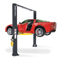
6. Tighten the gear ring bolts.
7. Verify the operation of the arm restraints by pulling
up on the key ring of the arm restraint pin. Pivot the arms
back and forth and test the operation of the arm
restraint pin in various positions. (See Fig. 14.6)
8. Ensure that the arms do not move when a force of
approximately 100 pounds or less is applied laterally to
the fully extended arms.
9. Adjust the gear ring on the arm as necessary to
ensure smooth operation and solid engagement of all four
arm restraint pin assemblies with the arm restraint gear
ring.
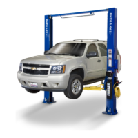
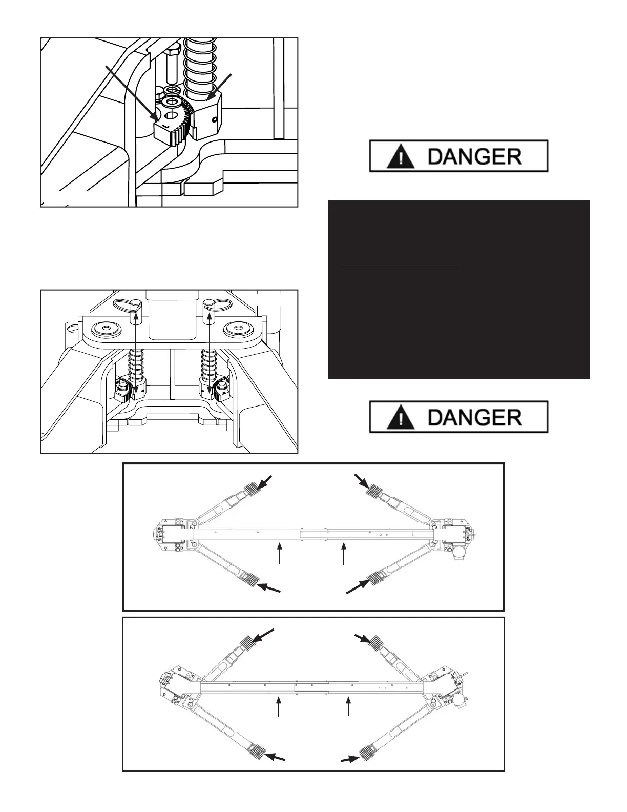
Fig. 14.7
Low Pro le Triple
Telescoping Arm
Assembly
Low Pro le
Medium Arm
Assembly
Approach
Fig. 14.5
Arm Restraint
Gear Ring
Arm
Restraint
Pin
Assembly
Fig. 14.6
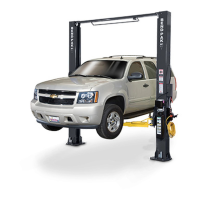
Fig. 14.8
Low Pro le Triple
Telescoping Arm
Assembly
Low Pro le
Long Arm
Assembly
Approach
NOTE:
EACH ARM RESTRAINT ASSEMBLY MUST BE IN-
SPECTED AND ADJUSTED AS NEEDED BEFORE
EACH AND EVERY TIME THE LIFT IS OPERATED.
DO NOT OPERATE THE LIFT IF ANY OF THE FOUR
ARM RESTRAINT SYSTEMS ARE NOT FUNCTIONING
PROPERLY.
REPLACE ANY BROKEN COMPONENTS OR COMPO-
NENTS WITH BROKEN TEETH ONLY WITH AUTHO-
RIZED OR APPROVED REPLACEMENT PARTS.