11
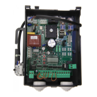
CP.B24 CONTROL UNIT
WIRE DIAGRAM
Wire connections shown in Fig. 1 are described hereunder:
Terminals Function Description
M+/M- Motor Quick connector for motor connection, 24VDC 120W max
COM
SWO
SWC
Limit switches
Quick connector for limit switch connection.
COM: Common to limit switches
SWO: Input, OPEN limit switches (N.C. contact)
SWC: Input, CLOSE limit switches (N.C. contact)
BAR/BAR SAFETY EDGE
Input, safety edge contact
Resistive edge: Closed “DAS” jumper
Mechanical edge: Open “DAS” jumper
If the safety edge is activated, the gate stops and the performs a movement reversion
for 3s
PED PEDESTRIAN
Input, pedestrian push-button (N.O. contact). It controls the partial opening of the gate
according to the value preset by TPED.
Active with completely closed gate.
It becomes “CLOSE” input with logics OPCL:ON or HTR:ON.
PHOTA Open Photocell Input, photocell activated in both opening and closing phases
PHOT Photocell Input, photocell activated in the closing phase only
STOP STOP Input, STP push-button (N.C. contact)
P.P. Step-by-Step
Input, step-by-step push button (N.O. contact)
It becomes “OPEN” input with logics OPCL:ON or HTR:ON.
+COM COMMON Common to all control inputs.
SHIELD/
ANT
Antenna
Antenna connection to the built-in receiver card
SHIELD: Shield/ ANT: Signal
FAST
24V
SLOW
0V
Secondary
Transformer
Inputs, connection of the secondary transformer
FAST: Input, 23V, it powers the motor during operation at normal speed
23V: power supply of accessories
SLOW: Input, 15V, it powers the motor during braking
0V: Input, 0V
IICH 2°Ch radio
Output, second radio channel of the built-in radio receiver.
N.O. contact, power-free.
+ 24V - 24 VAC/DC
Output, power supply of accessories, 24VAC/0.5A max.
CAUTION: in the event of installation of the battery loader card CB.24V, the output
(without mains power supply) will feature a voltage of 24VDC - polarised.
Check the correct connection of devices.
BLINK Flashing light Connection of the ashing light, 24VDC 15W max.
SCA SCA Open gate warning light 24Vac output.
ENCODER Encoder
Connector for the connection of the position sensor (encoder), integrated in the motor.
TO CHECK CONNECTIONS
Before programming the control unit, check that the motor is correctly connected:
1) Cut off power supply.
2) Manually release the gate leaf, move the same at approx. half stroke and block it again.
3) Power the system again.
4) Press key <-> to send a step-by-step control signal.
5) The door leaf should open. If not, use the logics MINV to reverse the rotation direction of the motor and the limit
switches (see Fig.3).
6) Carry out the self-learning of the stroke and trigger thresholds, as shown hereunder in the AUTO menu.

 Loading...