15
STROKE LEARNING
For a correct operation of braking (with SLD logic: ON) it is essential that the stroke is memorised. This can be performed
either using the above described AUTO function or when the rst operation is completed (then carried out without inter-
ruptions) from open limit switch to close limit switch (or viceversa).
During the stroke learning the activation threshold values of the PMO and PMC anti-crash sensor and, if a slowing down
is required, the PSO and PSC values (SLD:ON logics), are also calculated.
However, these values can be manually modied at a second time.
If the encoder is activated, the position of the gate leaf is stored in memory and reset also in case of power failure.
If the encoder is disabled, in case of power failure a new complete operation will be required to memorise the stroke and
reset braking.
Note: If the automatic system is released and manually operated, the following operation might not perform braking cor-
rectly. Also in this case a new complete operation will be required to reset the regular operation of the system.
FUSES
In the event of malfunction or faults, check that fuses are in good condition:
Fuse 1: Protection of control logics
Fuse 2: Protection of 24VAC/DC accessory power supply output
Fuse 3: Protection of 230V/115V line
DIAGNOSTICS
One segment of the display is linked to each input. In the event of failure it switches on according to the following
scheme.
N.C. inputs are represented by the vertical segments. N.O. inputs are represented by the horizontal segments.
ERROR MESSAGES
The control unit checks the correct operation of the safety devices. In the event of faults the following messages can be
displayed:
ERR Error : self-setting of the amperometric device or storage of remote control codes in memory.
ERR1 Error : faulty encoder.
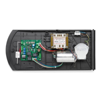
EMERGENCY BATTERY
In case of power failure, an optional accessory to power the control unit is available.
The kit is composed of CB.24V battery charge card and two rechargeable batteries at 12V/1,2Ah, which can be tted on
the back on the control unit container.
The CB.24V card must be connected between the secondary transformer and the 0/SLOW/24V/FAST inputs, as shown in
the diagram of Fig.2.
During mains powered operation, the DL2 green LED is switched on and the card maintains the battery charged.
If no mains power is available, the card powers the system through batteries, the DL1 red LED switches on.
A F10A fuse protects the control unit during operation with an emergency battery.
If no main power is available and batteries are down, both LED’s are switched.
The buffer battery works and progressively runs down until it reaches the value of 18V. When this value is reached, the
battery is disconnected.
During operation in case of power failure, the output, 24VAC accessories of the control unit, is polarised.

 Loading...