12/ 2017
BENNING PV 2
19
Parts subject to wear:
- The BENNING PV 2 is provided with two fuses for overload protection:
One fuse with a nominal current of 500 mA, F, 1000 V, breaking capacity ≥ 1000 A, D =
6.3 mm, L = 32 mm (P.no. 749771)
- The BENNING PV 2 is supplied by six 1.5 V batteries/ type AA (IEC LR6).
Note on optional accessories:
- PC software BENNING SOLAR Manager for the creation of test reports and documentation
in compliance with VDE 0126-23 (DIN EN 62446) and VDE 0126-24 (DIN EN 61829) (part
no. 050423).
- Insolation and temperature measuring instrument BENNING SUN 2 for measuring the inso-
lation (W/m²), the PV module temperature and the ambient temperature (P.no.: 050420).
- Temperature sensor with suction cup for BENNING SUN 2 for attachment to the rear of the
PV module (part no. 050424).
- PV module holder for BENNING SUN 2 for safe attachment to the PV module (part no.
050425).
- AC/ DC current clamp adapter BENNING CC 3 for connection to the BENNING PV 2. The
measured AC/ DC current values can be stored in the memory of the BENNING PV 2 and
can be recalled (P.no. 044038).
- 40 m measuring leads BENNING TA 5 with practical rewinder and supporting loop. Connec-
tion: 4 mm safety test socket/ plug (P.no. 044039).
- Test badges "next test", 300 pieces (P.no. 756212)
- Test certicate forms for "Testing of PV systems" are available for download free of charge
at www.benning.de
4. Unit description
See gure 1: Appliance front face
See gure 2: Top side of the device
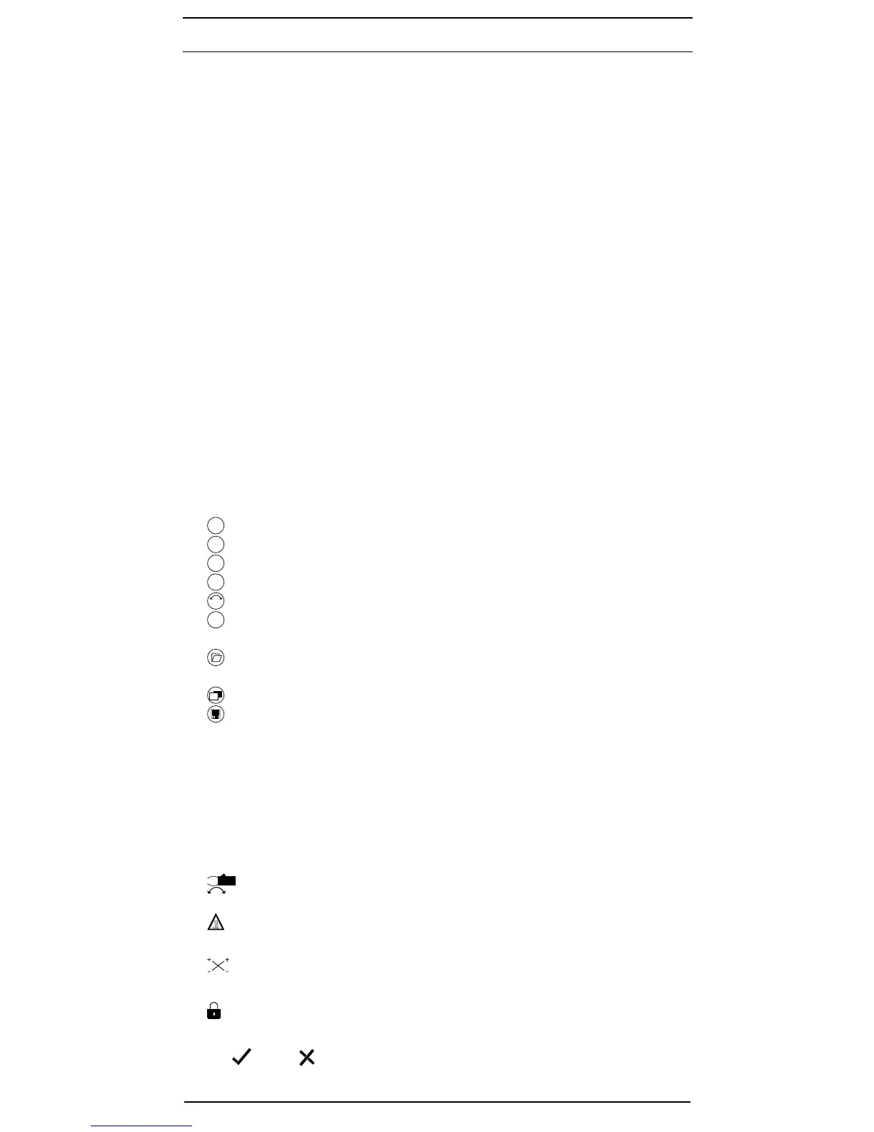
See gure 3: Digital display
The display and operator control elements specied in Fig. 1, 2 and 3 are designated as follows:
1
Digital display, indicates the test progress and individual measuring results,
2
R
PE
-key, for testing the protective conductor resistance
3
Auto
-key, for starting the automatic PV testing procedure
4
R
ISO
-key, for testing the insulating resistance (2-pin)
5
Mode
-key, selecting the test procedures
6
Ω
NULL
-key, for carrying out a null balance of the measuring lead resistances
7
V
ISO
-key, for selecting the testing voltage for insulating resistance measurement
8
NFC sensor, for data transmission to an Android device
9
-key, for calling stored measured values (display values)
J
USB interface (Micro-B socket), for connection of the USB connecting cable
K
1
-key, switch-over of LC display
L
-key, for storing the displayed measured values (display values)
M
+ PV test socket (red), for connecting the red safety measuring lead with PV connector
N
- PV test socket (black), for connecting the black safety measuring lead with PV connector
O - 4 mm test socket (black), for connecting the safety measuring lead with probe tip/ alliga tor
clip
P + 4 mm test socket (red), for connecting the safety measuring lead with probe tip/ alligator
clip
Digital display:
A RPE voltage polarity indication, indicates the polarity of the DC voltage at the 4 mm test
sockets
O
and
P
. For AC voltage, “+” and “–“ are displayed alternately.
B Current clamp measurement enabled
C
NULL
R
PE
null offset, is displayed in case of a compensation (null balance) of the measuring
lead resistance
D
Attention, hot surface! If the symbol is displayed, immediately disconnect the
BENNING PV 2 from the PV generator. Connect the BENNING PV 2 only after the symbol
has disappeared.
E Polarity indication, indicates the polarity of the DC voltage at the PV test sockets
M
and
N
F
c
Attention, dangerous voltage has been detected
G R
PE
LOCK, enabled, if a continuous RPE measurement has been activated
H
m
Attention, if this symbol is activated, observe the instructions contained in the operating
manual in order to avoid danger.
I R
ISO
(PASS)/ (fail), indicates whether the measured insulating resistance is within the
preset limiting values
J Selection of the insulation test voltage, displays the testing voltage of the insulating re-