12/ 2017
BENNING PV 2
25
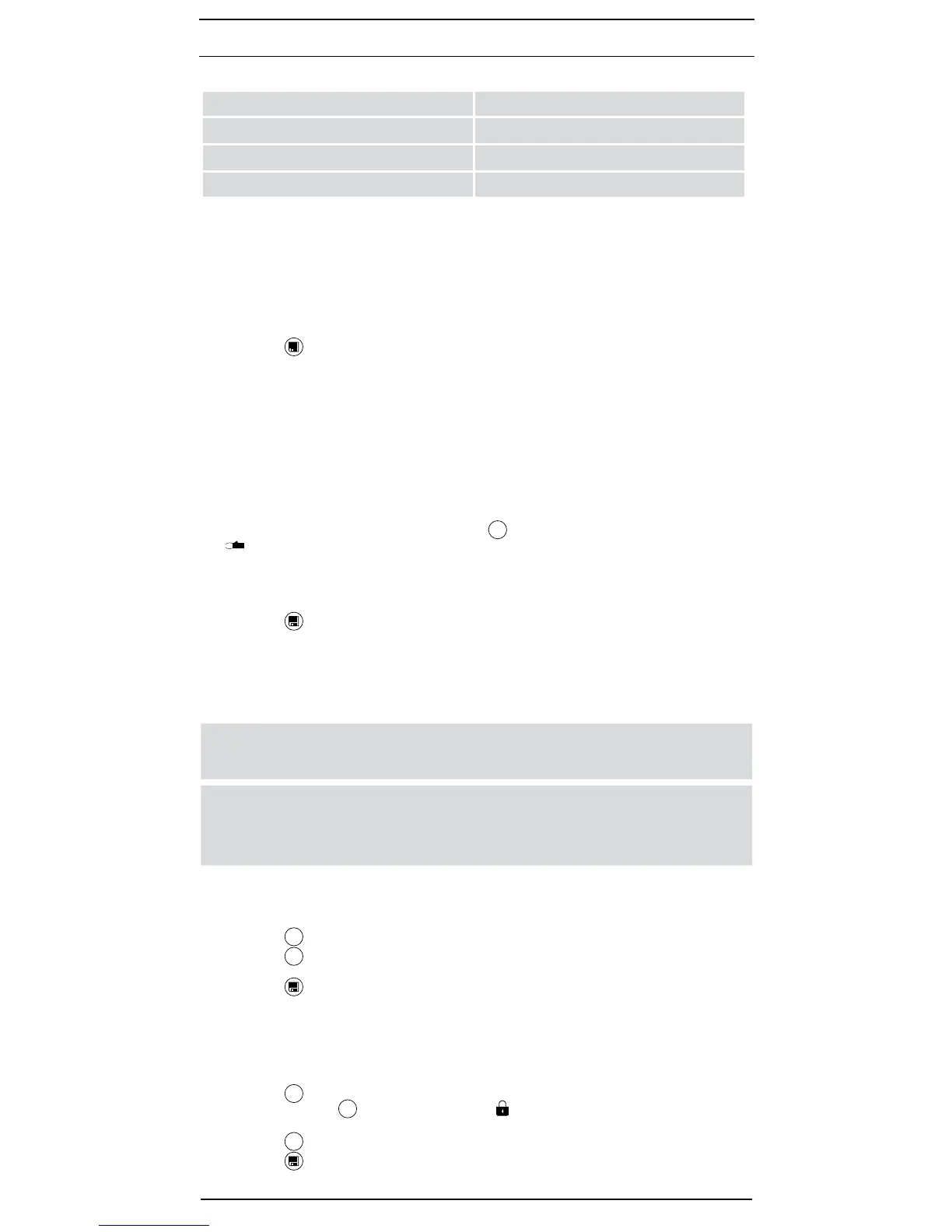
Preset limiting values:
V
ISO
Limiting value of insulating resistance
250 V 0.5 MΩ
500 V 1.0 MΩ
1000 V 1.0 MΩ
8.4 AC/ DC voltage measurement
- Disconnect the PV safety measuring leads from the PV test sockets
M
and
N
.
- Connect the red and black safety measuring lead to the corresponding 4 mm test sockets
P
and
O
.
- Connect the measuring probes to the voltage source to be measured.
- The BENNING PV 2 automatically measures the voltage at the measuring probes.
- The polarity of the DC voltage is displayed by “+ / –“ A. In case of AC voltage, “+ / –“ A will
be displayed alternately.
- Press the key
L
to store the measured value to the next storage location available.
See gure 7: Voltage measurement via 4 mm test sockets
8.5 Current measurement by means of optional AC/ DC current clamp adapter
BENNING CC 3 (part no. 044038)
By means of the optional AC/ DC current clamp adapter BENNING CC 3, the BENNING PV 2
can be used to measure the operating current of a PV system. The determined current values
can be stored in the internal memory of the BENNING PV 2 and can be recalled.
- Disconnect all measuring leads from the BENNING PV 2.
- Connect the BENNING CC 3 current clamp adapter to the 4 mm test sockets
P
and
O
of
the BENNING PV 2.
- Switch on the BENNING CC 3 current clamp adapter and select the 40 A range.
- Switch on the BENNING PV 2 and press the
Mode
-key
5
to select the Mode
d
. The symbol
B for current clamp measurement is displayed.
- For direct current (DC) measurements, press the null balance key (ZERO) of the BENNING
CC 3 until a current value of approx. 0 A is displayed.
- Enclose the single-wire live conductor by means of the current clamp adapter.
- The measured current will be shown on the display
1
.
- Press the -key
L
to store the measured value to the next storage location available.
See gure 8: AC/ DC current measurement by means of optional current clamp adapter
BENNING CC 3
8.6 Insulating resistance measurement R
ISO
(2-pin)
The BENNING PV 2 can be used for measuring the insulating resistance between two measu-
ring points. To do this, use the enclosed safety measuring lines and 4 mm alligator clips.
c
The PV generator must be isolated from the electric power supply!
Neither the positive nor the negative pole of the PV generator must be earthed!
m
If a voltage of > 30 V is applied to the test object, the determined voltage will
be displayed and the R
ISO
measurement will be blocked! Do not connect the
measuring probes to a voltage source during R
ISO
measurement, as the built-in
fuse of the BENNING PV 2 might trip!
For single measurement:
- Make sure that the switching circuit and/or the test object are free of voltage.
- Connect the red and black safety measuring leads to the corresponding 4 mm test sockets
P
and
O
and connect the test object.
- Press the
V
ISO
-key
7
to select the desired testing voltage (250 V, 500 V or 1,000 V DC).
- Press the
R
ISO
-key
4
.
- The measured insulating resistance R
ISO
will be shown on the LC display
1
.
- Press the -key
L
to store the measured value to the next storage location available.
see gure 9: Insulating resistance R
ISO
(2-pin)
For continuous measurement:
- Make sure that the switching circuit and/or the test object are free of voltage.
- Connect the red and black safety measuring leads to the corresponding 4 mm test sockets
P
and
O
and connect the test object.
- Press the
V
ISO
-key
7
to select the desired testing voltage (250 V, 500 V or 1,000 V DC).
- Press and hold the
R
ISO
-key
4
until the symbol G is displayed.
- The measured insulating resistance R
ISO
will be shown continuously on the LC display
1
.
- Press the
R
ISO
-key
4
to terminate the continuous measurement.
- Press the -key
L
to store the measured value to the next storage location available.
see gure 9: Insulating resistance R
ISO
(2-pin)