EasyManua.ls Logo

Benning PV 2 - Page 4

Benning PV 2
Print Icon
To Next Page IconTo Next Page
To Previous Page IconTo Previous Page
Loading...
12/ 2017
BENNING PV 2
D
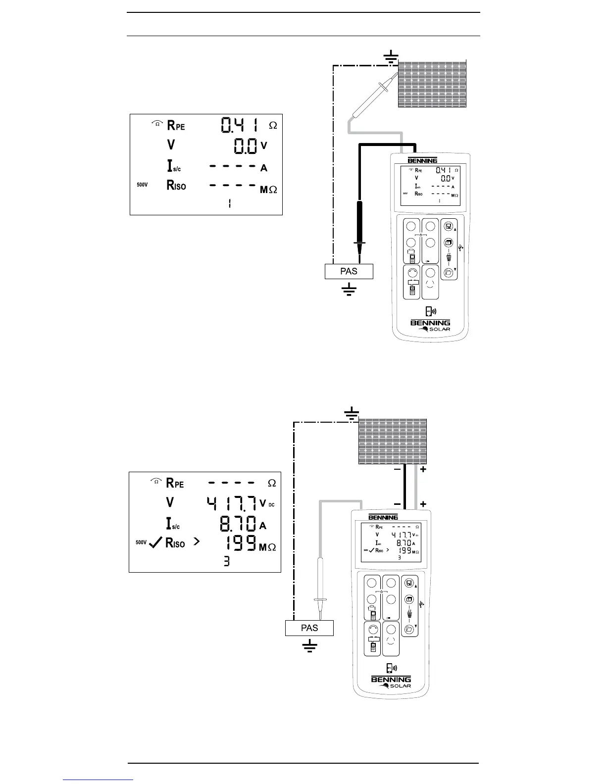
Bild 5: Prüfung des Schutzleiterwiderstandes R
PE
Fig. 5: Testing the protective conductor resistance (R
PE
)
Bild 6: Automatische Solarmodul-Messung, ISO-
Messung über Erdleiter
Fig. 6: Automatic solar panel measurement, ISO
measurement via earthing conductor
500V
250V 1000V
PV 2
DIN EN 62446 (VDE 0126-23), DIN EN 61829 (VDE 0126-24)
Auto Mode
a Vo/c, Is/c, MΩ
b Vmpp, Impp, FF
c a + b
d
Auto
Ω
NULL
R
PE
Mode
R
ISO
V
ISO
NULL
R
PE
500V
250V 1000V
PV 2
DIN EN 62446 (VDE 0126-23), DIN EN 61829 (VDE 0126-24)
Auto Mode
a Vo/c, Is/c, MΩ
b Vmpp, Impp, FF
c a + b
d
Auto
Ω
NULL
R
PE
Mode
R
ISO
V
ISO
NULL
R
PE
500V
250V 1000V
PV 2
DIN EN 62446 (VDE 0126-23), DIN EN 61829 (VDE 0126-24)
Auto Mode
a Vo/c, Is/c, MΩ
b Vmpp, Impp, FF
c a + b
d
Auto
Ω
NULL
R
PE
Mode
R
ISO
V
ISO
NULL
500V
250V 1000V
PV 2
DIN EN 62446 (VDE 0126-23), DIN EN 61829 (VDE 0126-24)
Auto Mode
a Vo/c, Is/c, MΩ
b Vmpp, Impp, FF
c a + b
d
Auto
Ω
NULL
R
PE
Mode
R
ISO
V
ISO
NULL
c
Max.
P ≤ 10 kW
Vo/c ≤ 1000 V
Is/c ≤ 15 A
c
Nicht an
parallel
geschalteten
PV-Strängen
messen!
Do not
make
measurements
at PV strings
which are
connected in
parallel!
PV-Modul/ -Strang
PV-module/ -string
PV-Modul/ -Strang
PV-module/ -string

Table of Contents

Other manuals for Benning PV 2

Related product manuals