8
caldaie
DHW
OUT IN
1.6 DESCRIPTION OF OPERATING
PRINCIPLES
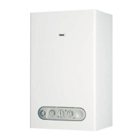
1.6.1 Hydraulic operating principle in DHW
(Fig. 1.23)
When service water taking cock (1) is opened, system water
flows back to DHW input (2), through capacity regulator (3)
and the flow-meter (4). Water getting through the flow-meter,
exceeding a 2,5 l/min capacity, pushes float, located inside it,
upward. This movement allows closing the electric contact,
located in a device out of the flow-meter. By a connection ramp
(5), water flows from flow-meter to flow limiting device (6)
and then into bi-thermal exchanger (7).
1.6.2 Electric operating principle in DHW
(see APPENDIX - E pages 81, 82)
In order to get hot water ready only, in summer, set function
selector on « » DHW symbol. When hot water cock is
opened and capacity exceeds 2,5 l/min, the flow-meter,
measuring water flowing through the circuit, check pressure
switch closing by electric enabling; the pressure switch starts
ignition sequence:
- C.A.I. version:
When activated, water pressure switch enables ignition; gas
valve operating devices are fed.
- C.S.I. version:
When activated, water pressure switch feeds the fan, while
gas valve operating devices are fed.
Under temperature request condition, the burner switches on
and gas solenoid valve proportionally opens shutter to allow
slow burner ignition - automatically adjusted by microprocessor
- then maximum power is reached until temperature set on
selector is obtained.
According to taking capacity, burner flame automatically fits
hot water requests.
Both temperature selector and sensor provide for a resistance
value to board integrated component, which, at the beginning
(cold) controls burner maximum operation, until temperature
read on secondary by NTC sensor, compared by main board
integrated component, with resistance set on DHW temperature
selector, approaches temperature set: then minimum level is
reached in modulation phase.
The burner switches off 5°C after temperature set and switches
on 1°C below.
Finally, when DHW cock is opened, the operating sequence is
the following:
C.A.I. version
Flow-meter
Water pressure switch check
Burner
C.S.I. version
Flow-meter
Water pressure switch check
Quiescent safety pressure switch
Fan
Safety pressure switch enabled
Burner
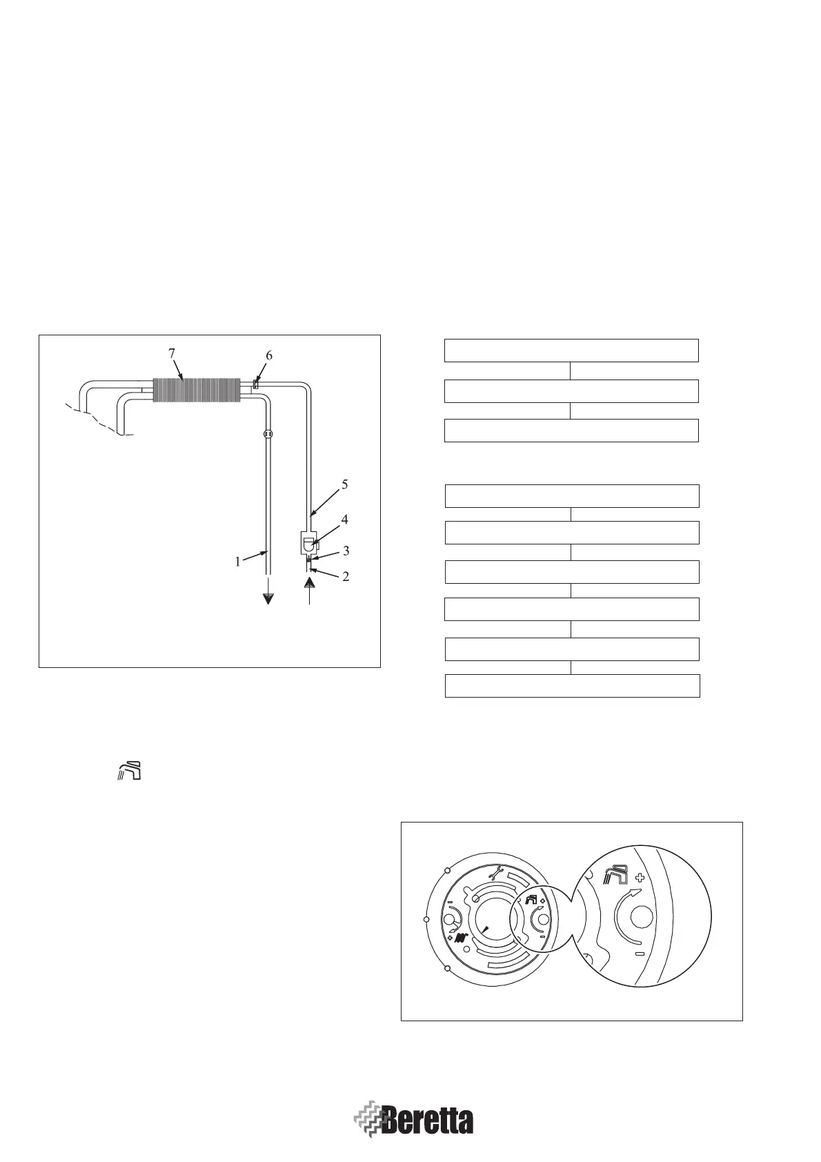
1.6.3 DHW temperature adjustment
To adjust DHW temperature (bathrooms, shower, kitchen, etc.)
to adjust CH temperature, remove function selector and act on
right potentiometer (Fig. 1.24).
Fig. 1.23
Fig. 1.24
 Loading...


