7
caldaie
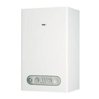
Solenoid valves
Modulator
that gas flowing to the burner is stopped very quickly under
any faulty condition.
The modulator is an integral part of the gas valve; the operator
modulates by changing the current to the coil to let the right
quantity of gas to flow to the burner (Sect. 1.5.1 page 3).
1.5.18 Safety valve
(POS. 16 APPENDIX - A page 77)
The safety valve is located underneath the circulator (Sect. 1.5.3
page 3) and has the job of protecting water circulation from
eventual over pressure caused, for example, by an increase in
the volume of primary fluid due to heating effect. The valve is
gauged to an operating pressure of 3 bar.
1.5.19 Expansion tank (POS. 17 APPENDIX - A page 77)
The expansion tank is located between the two uprights of the
framework and has the job of compensating the increased
volume of primary fluid from heating effect, thanks to the work
done by a rubber membrane loaded with nitrogen beforehand
at 1 bar.
It has been scaled to meet with all engineering solutions
normally used in domestic central heating units. The current
production expansion tank has a capacity of 8 l. and is adequate
for a system containing about 100 l. It may eventually be
integrated with an auxiliary if it should prove to be insufficient.
1.5.20 Fan (C.S.I. only)
(POS. 18 APPENDIX - A page 77)
The fan is located above the combustion chamber (Sect. 1.5.2
page 3) and serves to expel combustion products from the air
box (Sect. 1.5.11 page 5).
Specifically designed for this kind of application, it has the
characteristic of being absolutely silent with top performance.
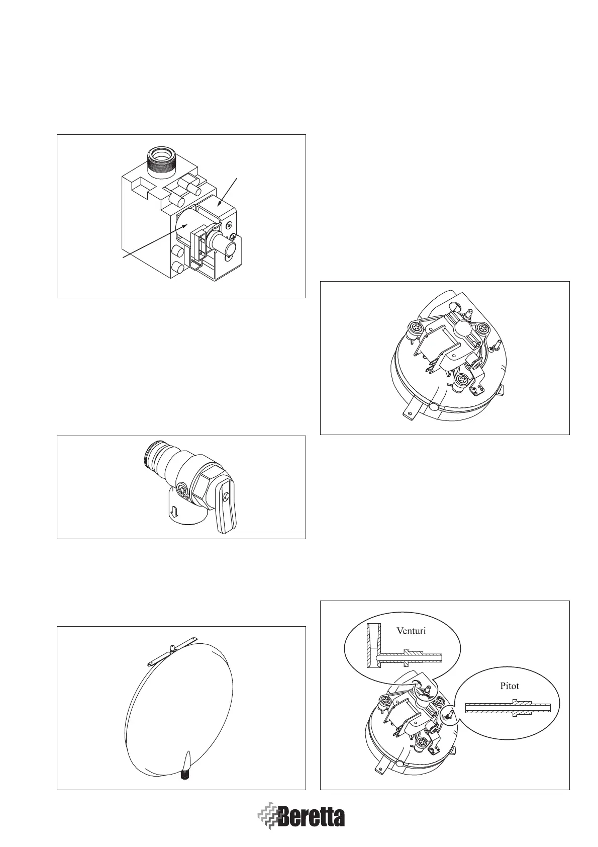
1.5.21 Venturi and Pitot tube (C.S.I. only)
(POS. 19 APPENDIX - A page 77)
The Venturi and Pitot tube are installed on the fan screw conveyor
(Sect. 1.5.20 page 7) and continuouslycorrect scavenging of
products of combustion.
The first device has the job of signalling static pressure value
as combusted gas flows through, while the second measures
the total pressure. The difference in pressure works on the safety
pressure switch membrane (Sect. 1.5.8 page 4), through two
small tubes, switching on the microswitch.
Fig. 1.19
Fig. 1.20
Fig. 1.21
Fig. 1.22
Fig. 1.18
 Loading...


