6
caldaie
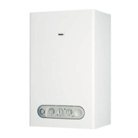
1.5.13 NTC temperature control probes
(POS. 12 APPENDIX - A page 77)
NTC probes, Negative Temperature Control, are located at the
exchanger outlet (Sect. 1.5.10 page 5) on the heating side and
on the outlet ramp of the exchanger on the sanitary side
respectively; they measure the temperature of primary and
secondary water for the electronic control panel.
These are thermistors where the value of the heating element
drops as the temperature rises.
The instantaneous comparison between effective temperature of
the water and the one set by the User causes a change in the
current sent to the gas valve modulator coil (Sect. 1.5.10 page 5).
1.5.14 Fumes thermostat (C.A.I. only)
(POS. 13 APPENDIX - A page 77)
The fumes thermostat is located on the upper right hand side of
the hood; it is a device for controlling correct evacuation of
combustion products.
Combustion products will be discharged through slits on the
side of the hood if the flue should be obstructed, heating up the
thermostat so that it starts working.
1.5.15 Limit thermostat
(POS. 14 APPENDIX - A page 77)
The limit thermostat is on the heating side of the exchanger
(Sect. 1.5.10 page 5) and serves to prevent the boiler from
boiling.
It is an automatically set contact device, which will interrupt
the flame detection electrical circuit, should it work at a
temperature of about 110°C.
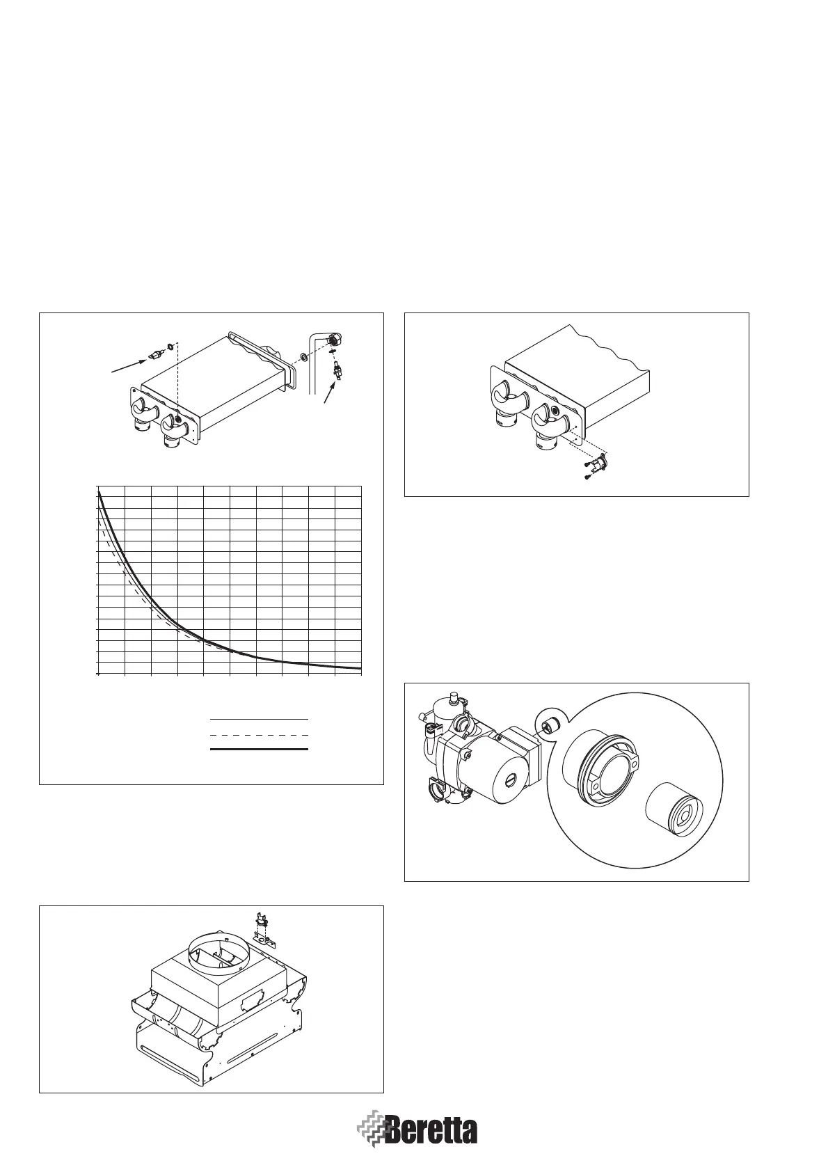
1.5.16 By-pass valve
The automatic by-pass is installed inside the duct
connecting the system’s delivery to CH return. Its job is to
guarantee primary water re-circulation in the boiler in
systems with high load loss.
The spring inside the by-pass valve is gauged to 530 gr. This
should be replaced with another one with increased capacity
if a high-headed circulator is used.
1.5.17 Gas valve
(POS. 15 APPENDIX - A page 77)
The gas valve is located under the combustion chamber (Sect.
1.5.2 page 3) and is the part designed to supervise burner
ignition, regulation and control operations.
The valve is made up of an aluminium pressofusion with two
solenoid valves, mechanically in series but parallel electrically.
The modulator is an integral part of the gas valve; the operator
modulates by changing the current to the coil to let the right
quantity of gas to flow to the burner. These configuration ensure
Fig. 1.14
Fig. 1.15
Fig. 1.16
Fig. 1.17
Heating
sensor
Sanitary
sensor
0 20 40 60 80 100
2000
4000
6000
8000
10000
12000
14000
16000
18000
20000
22000
24000
26000
28000
30000
32000
34000
0
RESISTANCE (ohm)
NOMINAL RESISTANCE
MINIMUM RESISTANCE
MAXIMUM RESISTANCE
TEMPERATURE (°C)
 Loading...


