EasyManua.ls Logo

Beretta Idrabagno Lx User Manual

Beretta Idrabagno Lx
154 pages
Go to English
To Next Page IconTo Next Page
Page #1 background imageLoading...
Page #1 background image
La rma Beretta en su constante mejora del producto, se reserva la posibilidad de modicar los datos de esta documentación en cualquier momento, sin previo aviso. Ref.: 09/2019
Servicio de Atención
al Cliente 902 446 446
Idrabagno Lx
Calentador de cámara estanca, bajo NOx
A
NEW
Riello SpA Sucursal en España
Pje. De Montserrat Isern, 1-3, 2º 1ª
08908 L’Hospitalet, Barcelona
Tel. 932 233 988 - Fax 932 233 483
www.berettaheating.com/spain
CARACTERÍSTICAS TÉCNICAS
u.d.m.
Tipología Cámara estanca
Encendido Electrónico
Control de llama Ionización
Modulación de llama Contínua
Producción de agua caliente con t 25°C
l/min 11,56 12,87 15,82
Potencia máxima nominal kW 22,5 25 30,00
Potencia máxima útil kW 20,16 22,45 27,60
AGUA
Campo de selección temperatura agua sanitaria ºC de 36 a 65
Presión mínima / normal / máxima bar 0,2 / 2 / 10
Caudal mínimo de funcionamiento en ACS l/min 2
Conexión agua
1/2”
GAS
Presión de alimentación nomimal MTN (G20) mbar 20
Presión de alimentación nominal GLP (G30 - G31) mbar 28/30 - 37
Conexión gas
3/4’
Temperatura de humos máx. G20 - G30 - G31 ºC 120 - 121 - 124 128 - 123 - 129 135 - / - 137
VALORES ELÉCTRICOS
Potencia absorbida W 41
Fusible A 2
Tensión de alimentación V-Hz 230 - 50
Grado de protección eléctrica IP X4D
TUBOS EVACUACIÓN HUMOS Y ASPIRACIÓN AIRE
Longitud máxima rectilínea - tubos concéntricos 60-100
m 3,5 2,6
Pérdida de carga por instalación codo adicional 45º / 90º m 1 / 1,5 1 / 1,5
Longitud máxima rectilínea - tubos separados 80
m 15 + 15 6 + 6
Pérdida de carga por instalación codo adicional 45º / 90º m 1,2 / 1,7 1,2 / 1,7
DIMENSIONES, PESO, GAS, COMBUSTIÓN, HOMOLOGACIÓN
Dimesiones (AltoxAnchoxFondo) mm 642 x 340 x 237 640 x 400 x 246
Peso kg 19 21
Código Producto gas disponible MTN 20143031 20143033 20143035 20143037
Código Producto gas disponible GLP 20143032 20143034 20143036 20143038
Homologación CE 51AP274
ESPECIFICACIONES ENERGÉTICAS
Idrabagno Lx
11
Idrabagno Lx
11 FLEX
Idrabagno Lx
13
Idrabagno Lx
17
Clasificación de eficiencia energética estacional en sanitario A A A A
Perfil de carga declarado
M M L L
Nivel de potencia sonora dB (A) 51 51 51 51
Diseño técnico
Leyenda: AGUA SANITARIA S= Salida GAS= G AGUA SANITARIA E= Entrada
Idrabagno Lx 11 FLEX - 13
Idrabagno Lx 17
IDRABAGNO Lx / Calentador de cámara estanca, bajo NOx
127
237
60
118
340
Ø60
74 74
Ø100
642
72 135 72 61
174
120
184
117
103
81
81
91
81
240
62
120
400
Ø60
74 74
Ø100
640
200 98 102
81
G ES
G ES
111
89
80
112

Table of Contents

Question and Answer IconNeed help?

Do you have a question about the Beretta Idrabagno Lx and is the answer not in the manual?

Beretta Idrabagno Lx Specifications

General IconGeneral
BrandBeretta
ModelIdrabagno Lx
CategoryBoiler
LanguageEnglish

Summary

Electronic Control and Management

Backlit LCD Display

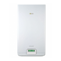
Overview of the new backlit LCD control panel with multiple functions and self-diagnosis.

Ecological Technology

Low NOx Burner Technology

Description of the new generation low NOx burner, with water-cooled operation.

Control Panel and Command Interface

Product Range and Model Identification

Indoor Installation Models

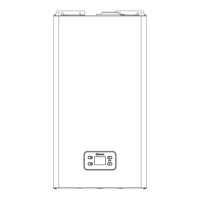
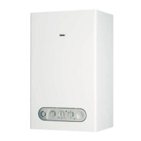
Details for indoor installation models, including codes and compatibility.

Outdoor Installation Models

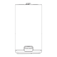
Details for outdoor installation models, including codes and compatibility.

1 WARNINGS AND SAFETY

2 DESCRIPTION OF THE APPLIANCE

Functional Elements, Dimensions & Connections

Overview of appliance components, maximum dimensions, and connection points.

Water Circuit Description

Description of the internal water circuit of the appliance.

Multi-Row Wiring Diagram

Provides the multi-row electrical wiring diagram for the appliance.

3 INSTALLATION

Installation Standards

Details the standards and regulations to be observed during installation.

Appliance Positioning Guidelines

Guidelines for selecting the optimal and safe location for the appliance.

Wall Mounting Instructions

Instructions and considerations for securely mounting the appliance to the wall.

Combustion Product Evacuation

Instructions for the safe discharge of combustion products.

Electrical Connection Guide

Detailed guide on making correct and safe electrical connections.

Gas Connection Procedures

Procedures and precautions for connecting the gas supply.

Water Connection Guide

Instructions for connecting the appliance to the water mains.

Anti-Freeze System Information

Information on the anti-freeze system for indoor and outdoor models.

Emptying the Water Heater

Steps for safely draining the water heater.

Gas Conversion Process

Procedures for converting the appliance between different gas types.

Boiler Adjustments and Settings

Guide to making necessary adjustments to the boiler's settings.

4 PUTTING INTO SERVICE

Control Panel Interface Explained

Explanation of the appliance's control panel and buttons.

Control Panel Icon Descriptions

Explains the meaning of the various icons displayed on the control panel.

Selecting Appliance Functions

How to navigate and select different functions on the appliance.

Appliance Initial Start-up Procedure

Step-by-step instructions for the initial commissioning of the appliance.

Fault Diagnosis and Reset Procedures

How to identify and resolve operating faults and reset the appliance.

Temporary Appliance Shutdown

Procedures for temporary shutdown of the appliance.

Preparing for Long-Term Disuse

Steps to take when the appliance will not be used for a long time.

Accessing Parameters Menu

Accessing and navigating the appliance's technical parameters menu.

Parameter Settings Table

A comprehensive table listing all adjustable parameters and their settings.

Resetting to Factory Settings

Instructions on how to restore the appliance to its default factory settings.

5 MAINTENANCE

6 REMOVING THE CASING

Indoor Model Casing Removal

Steps for removing the casing on indoor installation models.

Outdoor Model Casing Removal

Steps for removing the casing on outdoor installation models.

Accessing Modulation Circuit Board

Guide to accessing the modulation circuit board for maintenance or diagnostics.

7 TROUBLESHOOTING

8 TECHNICAL SPECIFICATIONS

Related product manuals