Frequency inverters must not be connected via a residual-current-operated circuit-
breaker as the sole protective measure!
The single exception below permits connection of a frequency inverter via a residual-cur-
rent-operated circuit-breaker as the sole protective measure:
Installation of a residual-current-operated circuit-breaker of the newest design for frequency in-
verters up to 4kVA (input voltage 1x230V) with MOBILE connection.This residual-current-
operated circuit-breaker must be suitable for alternating and pulsating DC leakage current.
Residual-current-operated circuit-breakers of this type bear the symbol .
Reliable tripping of the residual-current-operated circuit-breaker is not ensured in the
case of frequency inverters up to 4 kVA (input voltage 3x400V) with MOBILE connection;
an additional protective measure must be used for this reason. Also see the diagramm be-
low.
In the case of frequency inverters with PERMANENT connection (input voltage 1x230V
and 3x400V), another protective measure must always be used in addition to the residual-
current-operated protective device. Also see the diagramm below.
The protective function of the residual-current-operated circuit-breaker is no longer ensured due
to leakage currents from interface suppression capacitors in the inverter and DC-components in
the fault current. All devices connected to this residual-current-operated circuit-breaker (and per-
son touching them) are no longer protected in the event of a fault.
The pluggable terminal strips on the inverter (power connection terminals) must not be
plugged or removed when alive (DIN VDE 0160/pr EN50178).
The inverter will be destroyed if the mains feeder is confused with the motor cable.
The DC link capacitors must be reformed if the inverter you wish to connect has been out of ope-
ration more than a year. To do this, connect the inverter to voltage for approx. 30 minutes.The in-
verter should not be loaded by connected motors during forming.
12.3. Motor connection
Connect the motor cable to the U, V, W and PE terminals.
The inverter will be deactivated in the event of a short circuit at the terminals U, V, W.
We recommend PTC evaluation using commercially available devices to achieve effective protecti-
on of the motor.
If interrupting contacts (e.g. contactors or motor protection switches etc.) have to be installed
between the motor and inverter, the circuit must be configured so as to ensure that the ENABLE
signal (terminals 10/11) is deactivated before separation of the inverter/motor connection. A relay
switching time of approx. 30 ms suffices.
We recommend using output chokes for motor cable lengths over 20 m.
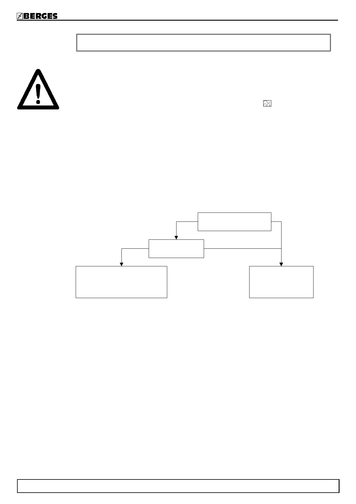
Connection of the electrical
equipment to the mains
Rated power
The compatibility of the electrical
equipment with the residual-current-
operated protectiv device must be
checked
Additional protection
besides residual-current-
operated protective device
is always necessary
Plugged in Permanent connection
>> 4kVA≤≤ 4kVA
BERGES electronic
16 Operating manual ACM-D2 29.05.98