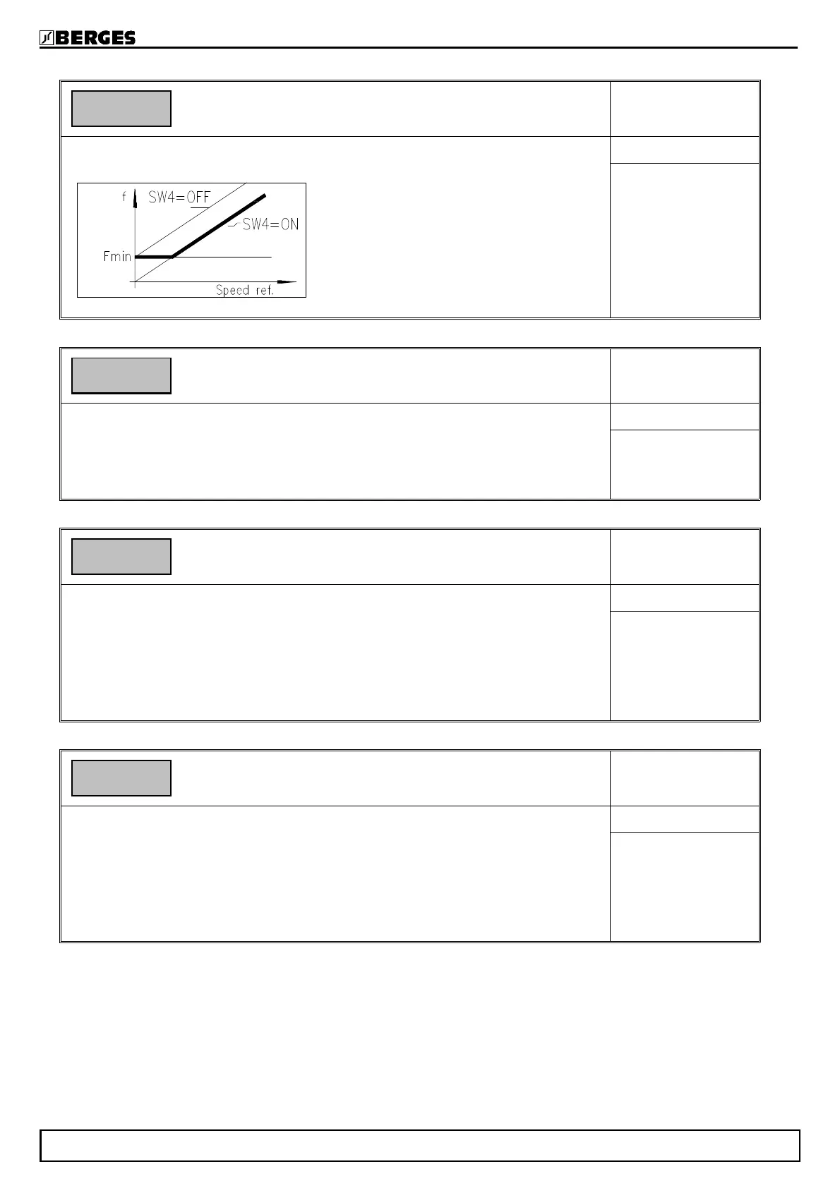
Function SW4: Fmin configuration
TAB3
This function defines the inverter behaviour at Fmin. Two different settings are possi-
ble (see the following diagramm).
SUB XPAR
Range: ON, OFF
Default: ON
Function SW5: Error signalling relay configuration
TAB3
This function defines when the fault relay ( term. 122,123,124) becomes active.
ON: Fault relais becomes active on fault or when the inverter is disabled.
OFF: Fault relais becomes active only on fault.
SUB XPAR
Range: ON, OFF
Default: ON
Function SW6: DC - Brake trigger
TAB3
ON: The DC-brake is activated automatically if the output frequency sinks
below the frequency threshold 1 (TAB1, funct. U) and the setpoint input
value is zero or manually by activating term. 30.
OFF: The DC-brake is ON if terminal is activated.
Indication: For the RESET to the DC-brake see configuration in TAB3,
SUBXPAR, function SW1.
SUB XPAR
Range: ON, OFF
Default: OFF
Function SW7: Autostart
TAB3
This function defines the start condition for line start (POWER-ON).
ON: With this setting, the inverter will turn on when the line power is applied and
the ENABLE and START/STOP-command is present.
OFF: Line start lockout. The inverter will not start upon application of the line
power. START/STOP or ENABLE must be opened, then closed to
start the drive.
SUB XPAR
Range: ON, OFF
Default: ON
SW4 ON
Fmin : Value TAB1, function 4.
f : Output frequency.
Speed ref. : Speed reference value.
SW5 ON
SW6 OFF
SW7 ON
BERGES electronic
29.05.98 Operating manual ACM-D2 47