Function OC2: Open collector output 2 (term. 22)
TAB3
Function OC2 defines the condition which will cause the open collector output OC2 to ope-
rate. It may be programmed to one of 11 conditions. The sign defines the output level for
OC1 (ACTIVE or NOT ACTIVE) at condition.
sign: +: NOT ACTIVE (HIGH) at condition.
- : ACTIVE (LOW) at condition.
code:
0: Motor speed greather than FX1 (TAB1, func. U).
1: Motor speed greather than FX2 (TAB1, func. u).
2: Motor has reached the end of the ramp. Indication at 0Hz included.
3: Motor speed = 0 Hz.
4: Motor speed = 0 Hz. Message at the end of the torque holding time
(see TAB1, func. 9).
5: Output current limit exceeded (TAB1, SUB IMOT, func. S).
6: Output current limit exceeded; Message at the end of the programmed delay
time (TAB1, SUB IMOT, func. DY).
7: +: Output activ or relay picks up when motor rotates in counter-clockwise
direction (CCW).
-: Output activ or relay drops out when motor rotates in clockwise
direction (CW).
8: The dynamic braking power is near the programmed limit
(TAB2, funct. BrLim).
9: Motor has reached the end of the ramp. Indication at 0Hz excluded.
10: The inverter (heat sink) temperature reaches the limit value.
(Only with Softw. D2A-STD)
11: The motor temperature reaches the limit value.
(Only with Softw. D2A-STD)
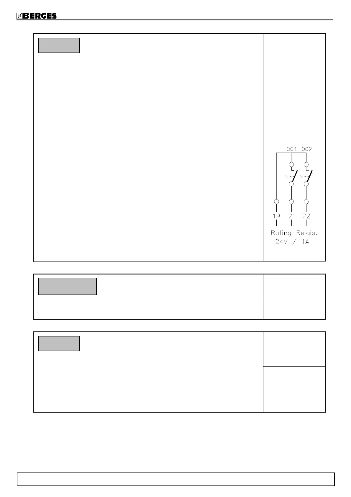
Option REL (see adjacent diagram):
Inverters which are equipped with the REL option possess relay outputs instead of the
two open collector outputs. Programming is performed by way of the functions OC1
and OC2. The switching states and switching conditions correspond to the above.
Range: −11..0..+11
Default: −0
Submenu Display indication
TAB3
This submenu defines what the display will indicate in TAB1, func. 1.
To enter the submenu press both SHIFT and SELECT simultaneously.
Function DIS: Display indication TAB1, func. 1
TAB3
Function DIS defines what the display will indicate in TAB1, func. 1.
0: Motorfrequency in Hz
1: Motorcurrent in % of rated inverter current (only with current meas. hardw.)
2: RPM for a 2-pole motor
4: RPM for a 4-pole motor
6: RPM for a 6-pole motor
8: RPM for a 8-pole motor
SUB DISP
Range: 0...8
Default: 0
OC2 −0
SUB DISP
DIS 0
BERGES electronic
50 Operating manual ACM-D2 29.05.98