36
POWER TAKE-OFF
All models are equipped with an inde-
pendent P.T.O. (profile DIN 15X12) - 1
speed at 1004 r.p.m. for the 1+1 and
2+2.
N.B. Always use the clutch lever when
wanting to engage or disengage the
P.T.O.
The p.t.o.’s rotation is clockwise.
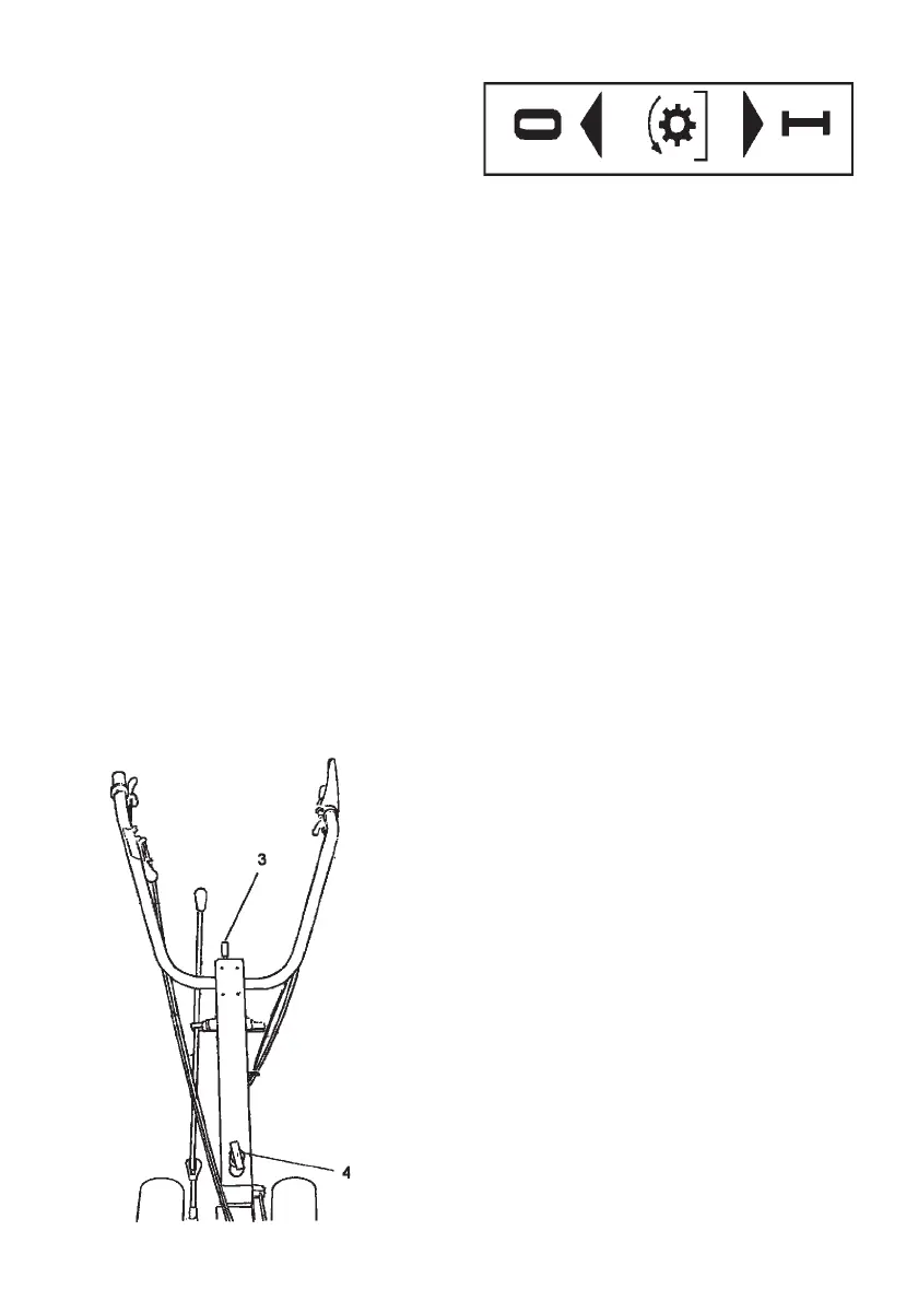
HANDLEBARS
Adjustment in height (vertical sense) al-
lows 6 positions, obtained with lever n°
3.
Side adjustment (horizontal sense) al-
lows 6 positions (3 with handlebars in
normal position + 3 with handlebars re-
versed by 180°), which are obtained with
lever n° 4
ROTATION OF HANDLEBAR FOR
USE WITH FRONTAL IMPLEMENTS
When assembling the frontal Implemen-
ts, the handlebars have to be rotated by
180°.
To rotate the handlebars proceed as fol-
lows:
Model 1+1 (Fig. 13A)
1. Put lever 5 on forward or reverse gear
position.
2. Remove lever from its support seat
10
3. Pull knob 4 upwards, turn the colu-
mn in direction of the arrow shown
on the plate located at the end of the
column (anti-clockwise rotation).
4. Turn lever 5 and put it back into its
support seat 10.
To bring the handlebars back to normal
position (tilling), repeat the same ope-
rations, while turning the handlebars in
anti-clockwise sense.
Model 2+2 (Fig. 14A)
1. Put lever 5 on forward or reverse gear
position.
2. Put lever 8 in 1st or 2nd speed posi-
tion.
3. Remove levers 5 and 8 from their
support seats 10.
4. Pull knob 4 upwards, turn the colu-
mn in direction of the arrow shown
on the plate located at the end of the
column (anti-clockwise rotation).
5. Turn lever 5 and 8 and put them back
into their support seat 10.
To bring the handlebars back to normal
position (tilling), repeat the same ope-
rations, while turning the handlebars in
anti-clockwise sense.
Fig 12A
 Loading...