N100
N100
S70S70
S40 S40
PR01
PR03
PR02
FP-01
FP-01
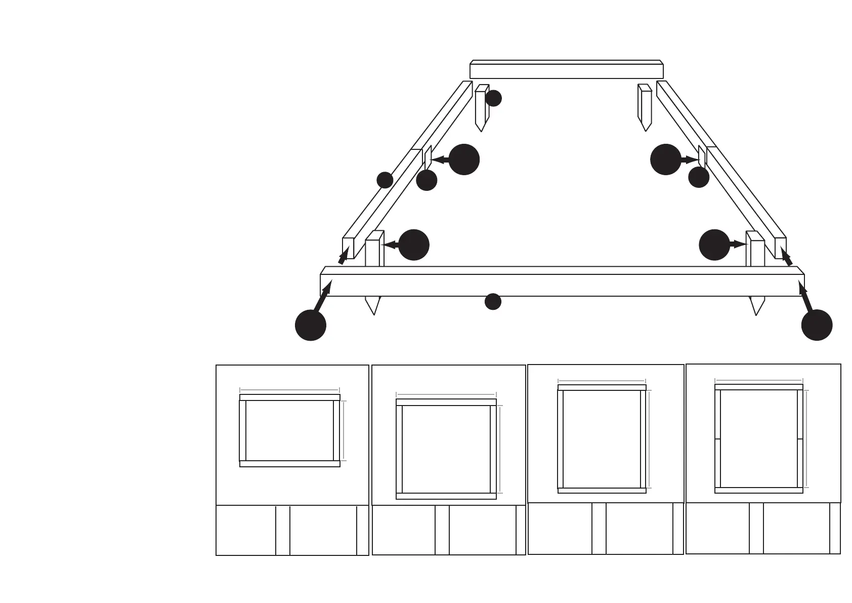
STEP 1: MEASURING YOUR SHED PRIOR TO ASSEMBLY OF ‘EZE BASE’
Measure the length of the building which is to be mounted on the
Eze Base and transfer these dimensions to the two outers supplied.
Mark accordingly and trial fit with the floor of the building.
STEP 2: LAYING OUT ALL PARTS
Lay all parts of the Eze Base in their intended place as
demonstrated by the illustration. This is to ensure
that all parts have been received.
For the 12’ greenhouses two conected JOISTS (PR02)
run down the sides and are fixed together with FIXING
PLATES (FP-01) and 40mm screws.
STEP 3: NAILING BEARERS AND JOISTS TOGETHER
Nail through the BEARERS (PR01) into either end of the
other JOISTS (PR02) with 100mm nails (N100). This is the
strongest way of securing the structure and the easiest. To
further strengthen the structure it is recommended that each
JOIST (PR02) end be
nailed in two equally spaced positions.
STEP 4: SQUARING OFF THE FRAMING
Measure across the diagonals, checking that both
measurements match, ensuring that the frame is
now square.
STEP 6: SCREWING THE CORNER SPIKES TO THE CORNERS AND
FIXING IN PLACE
Screw the four Corner Spikes (PR03) to each inner corner of the
base framing using 70mm screws (S70) ensuring the anchors are
flush with the top of the base frame. Then drive the Eze Base into
the ground to the desired height ensuring the base is level (use
spirit level).
Once fixed in position it is recommended that you pack any gaps
beneath the Eze Base and ground. This will help to protect the
base from weathering and create a neater finish.
STEP 5: SCREWING ‘L’ BRACKETS ONTO FRAME (OPTIONAL)
If the ground you wish to place your Eze Base and building on is
not level then it is necessary to add the ‘L’ brackets provided
to level out the Eze Base. Throughout this STEP use a spirit level to
assess progress. Screw the ‘L’ brackets where required from
the inside of the outer framing using 40mm screws (S40). Bear in
mind you may not need to use all the brackets.
NOTE: Any spare ‘L’ brackets can be used to strengthen the
corners.
EZE BASE CONSTRUCTION:
IMAGES ARE NOT TO SCALE
3’ x 6’
1812mm (6’ GABLE)
803mm (3’ DEPTH)
S40 40mm Screw
S70 70mm Screw
N100 100mm Nail
PR01 Bearer
PR02 Joist
PR03 Wood Spikes x4
PR04 Met ‘L’ Bracket x4
x16
x8
x8
x2
x2
IMAGES ARE NOT TO SCALE
6’ x 6’
1812mm (6’ GABLE)
1682mm (6’ DEPTH)
S40 40mm Screw
S70 70mm Screw
N100 100mm Nail
PR01 Bearer
PR02 Joist
PR03 Wood Spikes x4
PR04 Met ‘L’ Bracket x4
x16
x8
x8
x2
x2
IMAGES ARE NOT TO SCALE
9’ x 6’
1812mm (6’ GABLE)
2561mm (9’ DEPTH)
S40 40mm Screw
S70 70mm Screw
N100 100mm Nail
PR01 Bearer
PR02 Joist
PR03 Wood Spikes x4
PR04 Met ‘L’ Bracket x4
x16
x8
x8
x2
x2
IMAGES ARE NOT TO SCALE
12’ x 6’
1812mm (6’ GABLE)
3364mm (12’ DEPTH)
S40 40mm Screw
S70 70mm Screw
N100 100mm Nail
PR01 Bearer
PR02 Joist
PR03 Wood Spikes x4
PR04 Met ‘L’ Bracket x4
FP-01 Fixing Plate x2
x24
x8
x8
x2
x4
Please note these instructions are generic and cover a
range of buildings and not all items will be included.