KBF / KBF P (E5.2) 02/2012 page 19/103
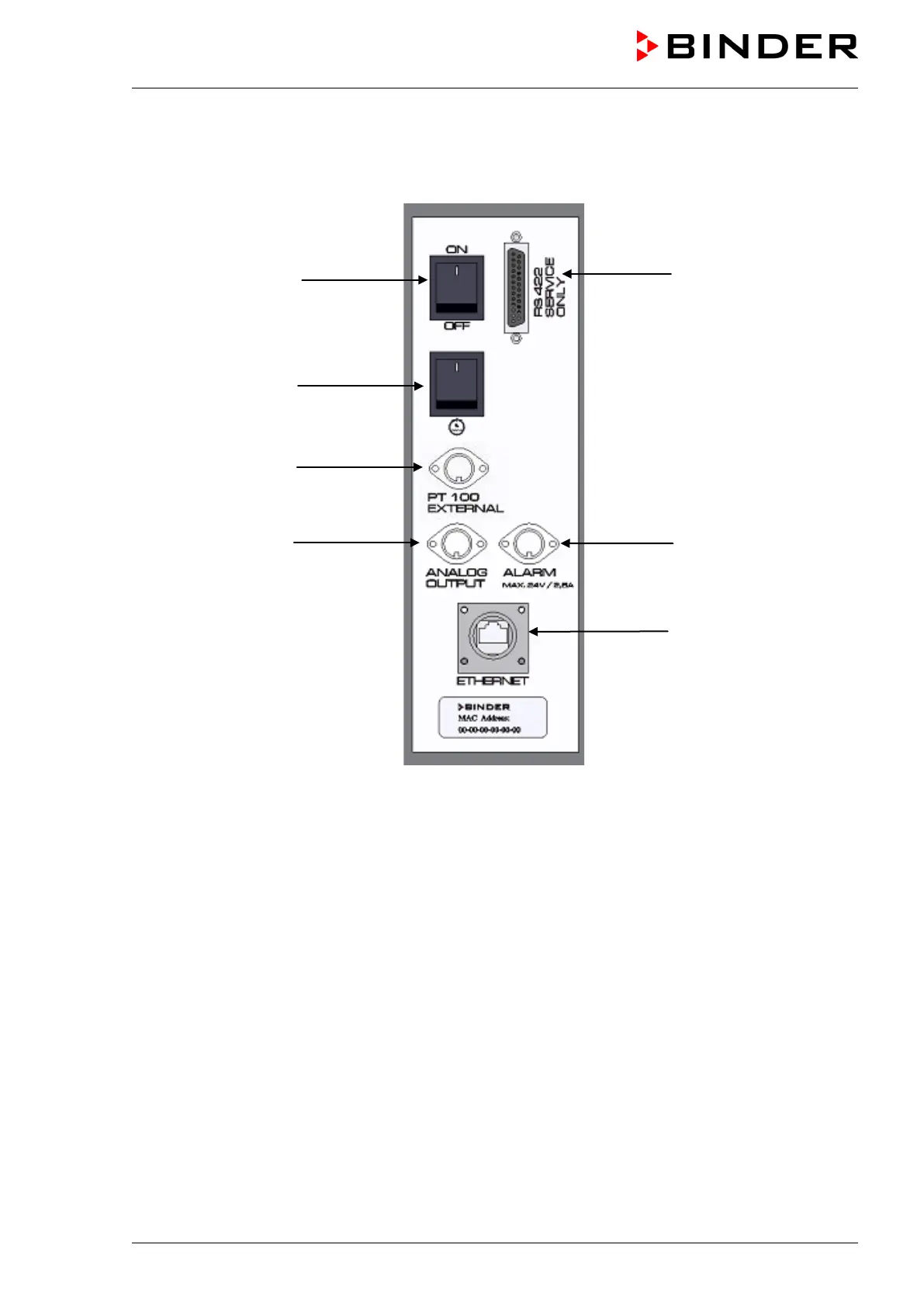
2.2 Lateral control panel, right side KBF / KBF P
(3)
(4)
(5)
(6)
(9)
(7)
(8)
Figure 6: Lateral control panel KBF / KBF P at the right side of the humidity module
with options analog outputs, alarm contact, and additional Pt 100 sensor
(3) Main power switch ON/OFF
(4) Humidity switch ON/OFF
(5) DIN-socket additional Pt 100 temperature sensor (option)
(6) DIN-socket analog outputs (option)
(7) DIN-socket alarm contact (option)
(8) Ethernet interface with indication of the MAC address for computer communication
(9) RS422 interface (for service purpose only)