MK / MKT (E5) 03/2019 page 19/158
(12)
(19)
(20)
(16)
(17)
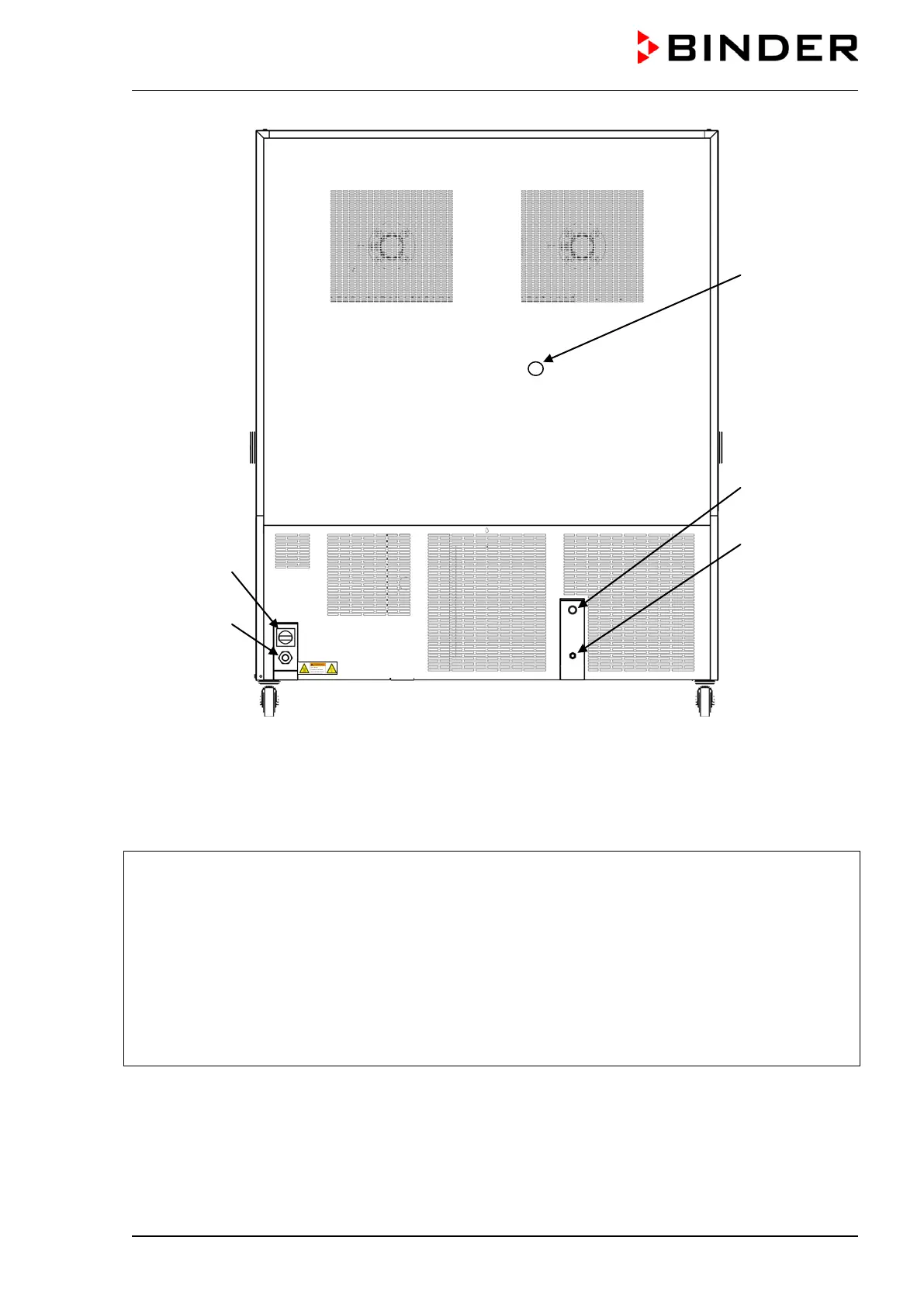
Figure 9: MK/MKT 115, 240, 720 rear chamber view
with options water cooling and compressed air connection (example: MK 720)
(12) Rear power switch
(13), (14), (15) not used
(16) Connection “OUT” for cooling water outlet with
screw thread ¾’’ for hose ½“, with union nut
(water cooling option, available via BINDER
Individual Customized Solutions)
(17)
Connection “IN” for cooling water inlet with
screw thread ¾’’ for hose ½“, with union nut
(water cooling option, available via BINDER
Individual Customized Solutions)
(18) not used
(19) Power connection
(20) Compressed air connection (option): Cou-
pling connector to connect compressed air
or the compressed air dryer (option)