VAP 1 / VAP 2 06/2020 Page 33/52
Proceed as described:
• Disconnect the power supply and secure it against being switched on again.
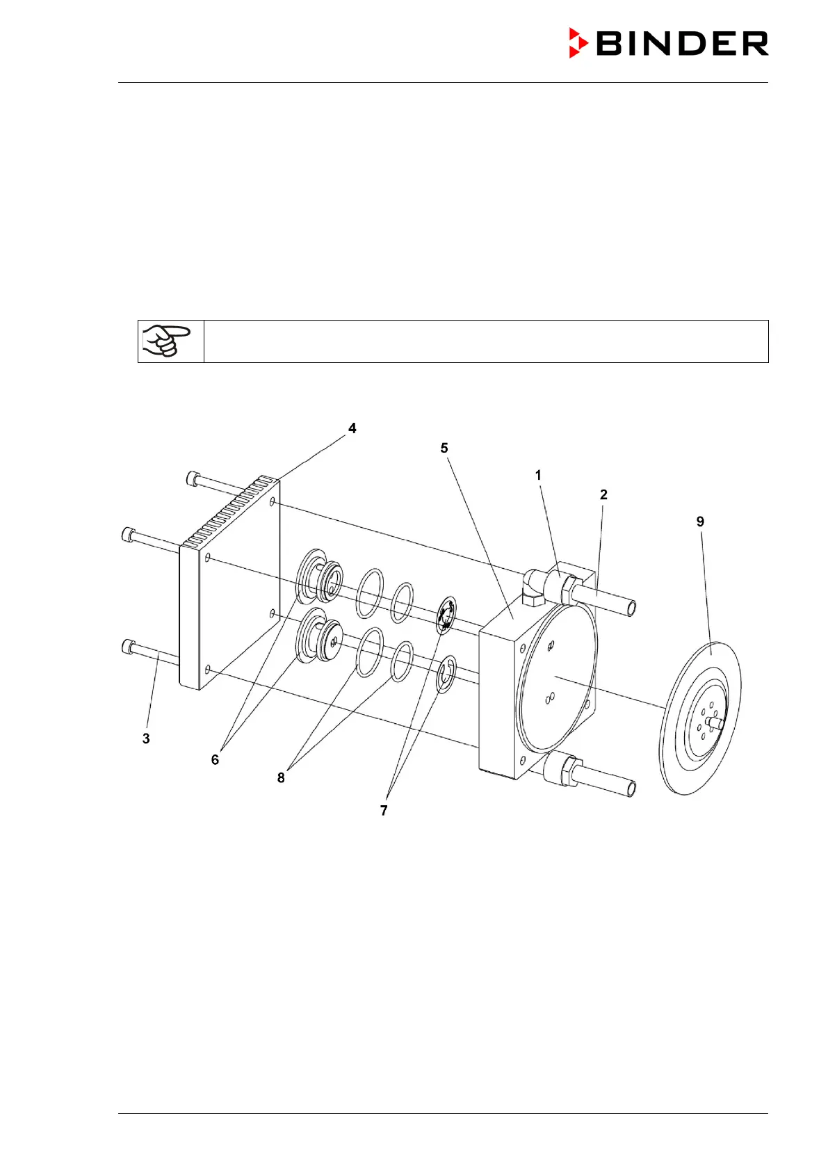
• Open the compression fittings (1) of the hoses (2) on the pump unit with an open end wrench size 17.
• On each heat dissipater (4) and pump head (5), remove the 4 cylinder screws (3) with an Allen wrench
size 4 mm.
• Lift the heat dissipater (4) and pump head (5) off. The valve inserts (6), valves (7) and O-rings (8) are
below the heat dissipater.
• Loosen the form diaphragm (9) by turning it counter-clockwise.
• Clean the pump head (5) and the form diaphragm (9) with a soft cleaning rag and acetone
NEVER use compressed air to clean these parts as they may be chemically
contaminated.
• Check the functionality of the drive.
Figure 11: Disassembly and assembly of the pump unit
(1) Compression fittings
(2) Hoses
(3) Cylinder screws
(4) Heat dissipater
(5) Pump head
(6) Valve inserts
(7) Valves
top: flap valve
bottom: standard valve
(8) O-rings
(9) Form diaphragm