Chapter 1 Motherboard Description
1-15
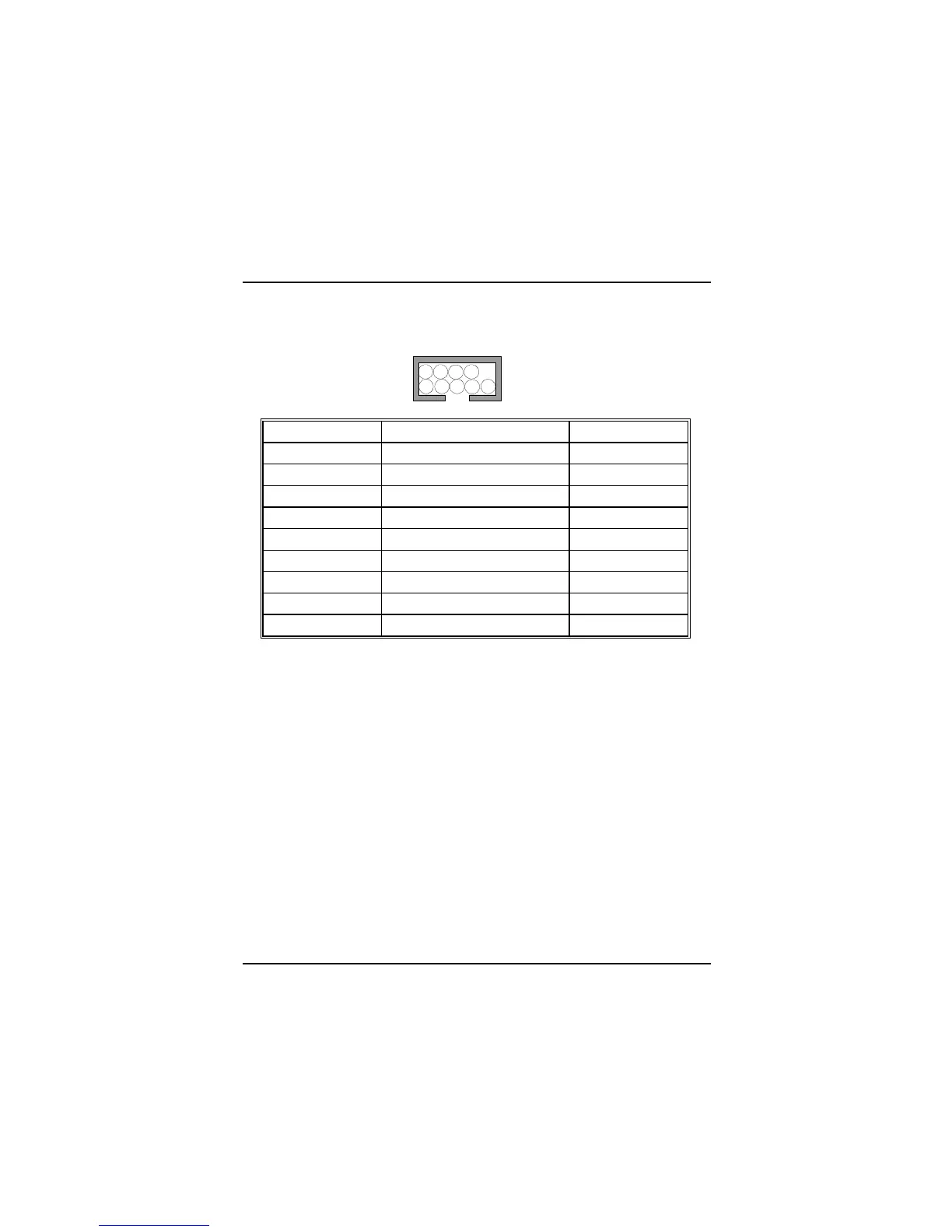
The Serial Interface Port-II : JCOM1
Signal Name IDC PIN
DCD Data Carrier Detect 1
RX Receive Data 2
TX Transmit Data 3
DTR Data Terminal Ready 4
GND Signal Ground 5
DSR Data Set Ready 6
RTS Request to Send 7
CTS Clear to Send 8
RI Ring Indicator 9
Special Applications
There are two types of serial devices that can be connected to a serial port. One of
the devices is called “DTE” (Data Terminal Equipment) and the other device is
called “DCE” (Data Communications Equipment). If a modem is connected to a
computer, for example, the modem is called the DCE and the computer is called
the DTE. In situations such as this, the pins on the serial ports can be connected
straight through.
In instances when there are two DTE devices connected together, such as a
computer and a printer, a special adapter called a “Null Modem” is needed to
make communication between the two devices possible.
When using the serial port to communicate between devices, one problem in
particular may arise. Some manufacturers use one set of signals to begin
communication with another device and other manufacturers do not use these
signals to initiate communication. If you encounter a communication problem that
cannot be resolved using a null modem, it can generally be assumed that one
device is using the initialization signals and the other device is not. This can
usually be resolved by wiring the RTS, CTS, and DCD pins together.
2
1
10
9



 To Next Page