Theory of Operation
13
Transmitter Monitoring
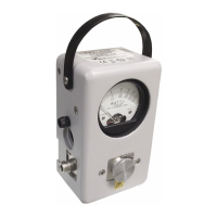
The Thruline Wattmeter can be used for the continuous monitoring of
transmitter output or reflected power, for instance in checking
intermittent antenna or line faults.
Component Testing
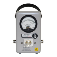
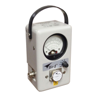
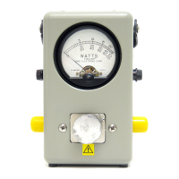
The Bird 43 is very helpful in component testing, and may be
employed in several ways:
1. VSWR or
φ may be measured by placing the component under test
between the wattmeter and a good load resistor.
2. Attenuation (power lost by heat in a line) as well as VSWR may be
measured by inserting the unknown line between two Thruline
wattmeters, or between a Thruline wattmeter and a Termaline
absorption wattmeter.
NOTE: Very small attenuations require allowance for normal
instrument errors. To correct for this without any calculations,
simply connect the wattmeters directly, with no line between
them, and adjust their zero settings until they are both zeroed.
3. Line loss using open circuit calibration: The high directivity of
elements can be exploited in line loss measurements, because of
the equality of forward and reflected power with the load
connector open or short circuited. In this state the forward and
reflected waves have equal power, so that
φ = 100% and ρ = ∞.
Open circuit testing is preferred to short circuit, because a high
quality open circuit is easier to create than a high quality short.
To measure insertion loss, use a high quality open circuit to check
forward and reverse power equality, then connect an open-circuited,