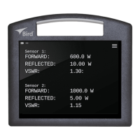
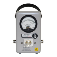
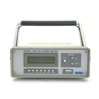
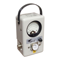
Model Differences
41
Maintenance
Do not make repairs to the probe assembly. If the sampler malfunc-
tions, we recommend returning the unit to the Bird Service Center for
repair. To replace the probe assembly, follow these instructions:
1. To reach the probe, unscrew the four 8-32 flat head screws
securing the back cover.
2. Grasp the back cover by the side tabs behind the line connectors
and pull straight backward to remove it.
3. Use a 1/16 hex socket wrench to remove the small coupling control
knob on the front of the wattmeter.
4. Remove the two 8-32 x 1/4” screws fastening the guide and plate
assembly to the back of the line section.
5. Put the control knob back on the shaft, then turn it counterclock-
wise until the collar is free of the shaft. Remove the control knob.
6. Pull the probe plate straight out of the pin and guide bushing.
7. Unscrew the 5/8 hex nut on the BNC connector and pull the
sampler connector into the case. The probe plate assembly, P/N
4431-003, is now released and may be replaced.
8. The sampler cable (RG-58/U) center conductor is soldered to the
probe’s rear stub. The cable is secured to the side sleeve of the
probe with the same screw used in the dc connector plug assembly,
P/N 7500-076. It may be removed by unscrewing the 3/8 hex
screw, unsoldering the lead tip and pulling out the cable. The
probe assembly is formed into the socket and is not replaceable.
9. Replace by carefully reversing the above procedures.
NOTE: When inserting the control bushing, be sure the alignment
pin is properly positioned.