ANTSPACE HK3 Water cooling container & Dry-Wet Tower Product Manual
21
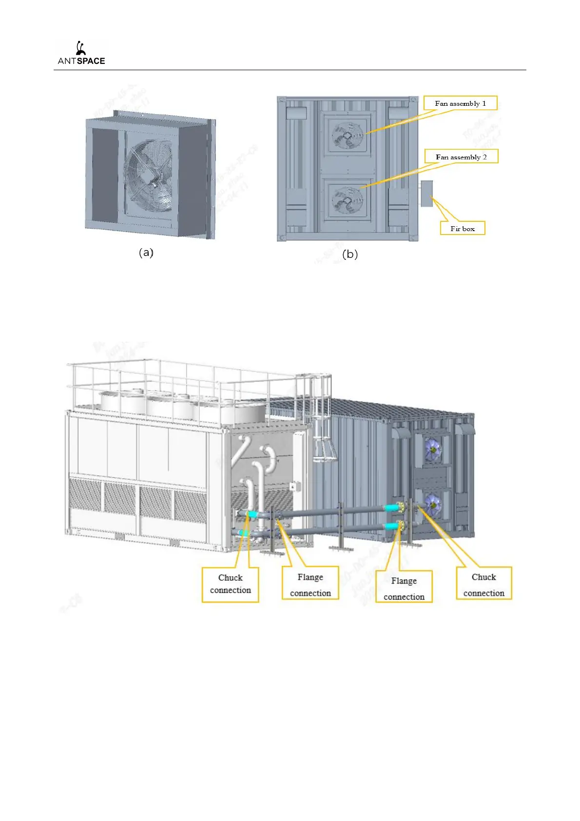
Figure 6-3(a)Schematic diagram of fan assembly(b)Installation diagram of container fans
6.4 Container Water Cooling System Pipeline Connection
Figure 6-4 Installation diagram of external pipelines
1) Pipeline connection:
a) Firstly, take out six pipelines numbered "BTMU XX-WBGL01", "BTMU XX-WBGL02",
"BTMU XX-WBGL03", "BTMU XX-WBGL04", "BTMU XX-WBGL05", "BTMU XX-
WBGL06","BTMU XX-WBGL07", "BTMU XX-WBGLZJ" and three sets of pipeline fixing