KT-210-424
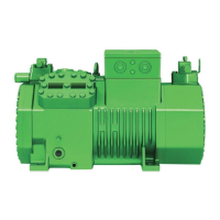
3.3 Dimensional drawings
1/8-27 NPTF
1 ( )HP
90
81
42
3 ( )LP
1/8-27 NPTF
M10x1,5
6
10
Ø12
5 / 8
7/16-20 UNF
SL
DL
241
198
Ø13
123
263
276
121
294
212223
525
401
37
358
269
Ø16 (5/8 )''
Ø22 (7/8 )''
18
221
Fig.3: 2DES-3.F1Y
241
125
310
155
K
G
198
7/16-20 UNF
5 / 8
SL
DL
202293
582
488
348
Ø12
M10x1,5
10
L
H
361
1 ( )HP3 ( )LP
1/8-27 NPTF1/8-27 NPTF
Ø13
2 ( )HP
1/8-27 NPTF
12611
7/16-20 UNF
7/16-20 UNF
16
M20x1,5
374
221
M
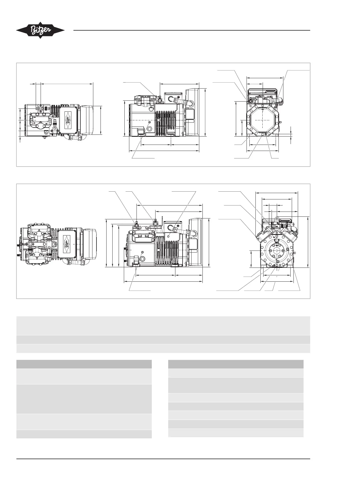
Fig.4: 4FE-5.F1Y, 4EE-6.F1Y, 4DE-5.F1Y, 4CE-6.F1Y
G
mm
H
mm
K
mm
L
mm
M
mm
DL SL
4FE-5.F1Y, 4EE-6.F1Y 56 317 37 306 354 Ø16 (5/8'') Ø28 (1 1/8'')
4DE-5.F1Y, 4CE-6.F1Y 64 325 42 310 368 Ø22 (7/8'') Ø35 (1 3/8'')
Connection points
1 High pressure connection (HP)
Connection for high pressure switch (HP)
2 Connection for discharge gas temperature
sensor (HP)
(4VE(S)-6Y .. 4NE(S)-20(Y): connection for
RI/CIC sensor as an alternative)
3 Low pressure connection (LP)
Connection for low pressure switch (LP)
4 CIC system: Injection nozzle (LP)
Connection points
4b Connection for RI/CIC sensor
4c Connection for RI/CIC sensor (MP / opera-
tion with refrigerant subcooler)
5 Oil fill plug
6 Oil drain
7 Oil filter (magnetic screw)
8 Oil return (oil separator)
8* Oil return for NH
3
with insoluble oil

 Loading...