KB-206-252
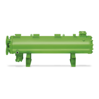
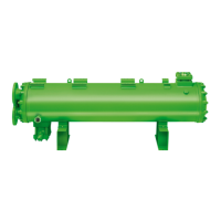
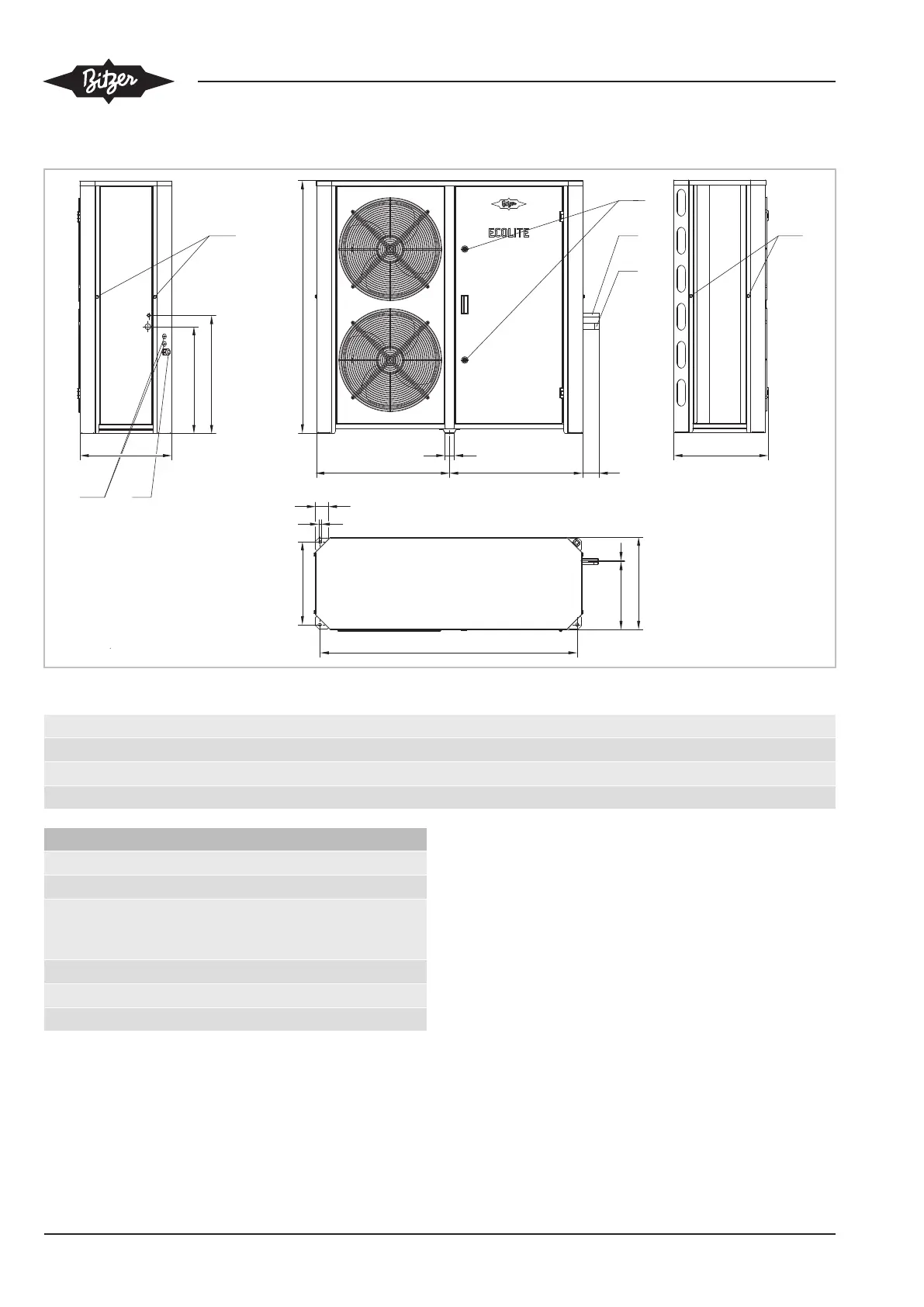
6.5 Connections and dimensional drawing
1
ØB
ØA
Y
X
648 80648
46
63
12
C
403
F
449
5
4
11
M8
11
M8
1253
12
M20
13
446 459
14
Fig.11: Connection positions (example shows LHL5E/4FES-3Y .. LHL5E/4CES-6Y)
Type ØA ØB C F X Y
mm mm mm mm mm mm
LHL3E/2EES-2Y .. LHL3E/2CES-3Y 22 12 830 334 520 568
LHL5E/4FES-3Y .. LHL5E/4CES-6Y 28 16 1230 332 520 575
Connection positions
1 Refrigerant inlet (suction gas line)
4 Refrigerant outlet (liquid line)
11 Load suspension points (maximum screw-in
thread length of the screws and the screw-in
eyes: 30 mm)
12 Plugs for screwed cable gland
13 Screwed cable gland (for cable Ø 9-17 mm)
14 Door lock (key enclosed)
Tab.4: Connection positions