KB-206-2 53
7 Electrical connection
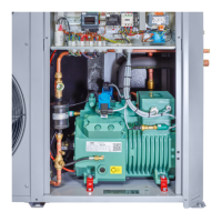
Semi-hermetic compressor, condenser fan and elec-
trical accessories correspond to the EU Low Voltage
Directive 2014/35/EU.
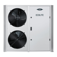
The ECOLITE condensing unit is provided exclusively
for the connection to TN-C-S or TN-S three-phase
power supply systems with a nominal voltage 230/400
V Δ/Y at a nominal frequency of 50 Hz. The connection
of a neutral conductor is mandatory. A nominal supply
voltage with qualitative characteristics according to DIN
EN 50160 is required. The ECOLITE condensing unit is
provided for a stationary installation.
Type gG fuses or line protection switches with C char-
acteristic must be provided.
Type Recom-
mended
fuse
Motor pro-
tection
switch set-
ting value
LHL3E/2EES-2(Y) 8 A 8.0 A
LHL3E/2DES-2(Y) 10 A 9.5 A
LHL3E/2CES-3(Y) 13 A 11.0 A
LHL5E/4FES-3(Y) 13 A 11.5 A
LHL5E/4EES-4(Y) 16 A 14.5 A
LHL5E/4DES-5(Y) 16 A 16.0 A
LHL5E/4CES-6(Y) 20 A 20.0 A
Depending on local conditions and applicable regula-
tions, a supply disconnecting device must be provided
on site. The service switch provided in the ECOLITE
condensing unit does normally not fulfil the require-
ments regarding an electrical disconnection of the
device.
7.1 Schematic wiring diagram for ECOLITE
condensing units
Abbr. Component
B1 Controller
B3 High pressure transmitter (liquid line)
B4 Low pressure transmitter (suction gas
line)
C1 Operating capacitor fan 1
C2 Operating capacitor fan 2
F2 Fuse rating 230 V
F3 Control circuit fuse
F5 High pressure switch
F6 Low pressure switch
K1 Main contactor
M1 Compressor
M1E Oil heater
M1Y1 CRII SV1
M1Y2 CRII MV2 (option)
M2 Fan 1
M3 Fan 2
M4 Additional fan
N2 Fan control module
OLC-K1 Oil monitoring (option)
Q1 Service switch
R3 Discharge gas temperature sensor
R4 Ambient temperature sensor
R5 Cold store temperature sensor (option)
R8 Suction gas temperature sensor
SE-B1 Protection device
S12 Door switch
T1 Control transformer
V1 Fan control module
Tab.5: Legend schematic wiring diagram ECOLITE