47
Gefahr!
Elektrischer Schlag!
Elektrische Ladung > 50 μC!
Lebensgefährliche Spannungen
auch nachdem die Spannungs-
zufuhr unterbrochen wurde.
An der Elektr(on)ik erst 5 Minu -
ten nach allpoligem Abschalten
der Spannung arbeiten!
• Sicher stellen, dass der FU, die
Ventilatoren und alle Sekundär-
geräte span nungs frei sind.
• Vor dem Berühren jede Klemme
und jedes Kabelende erden.
• Spannungsversorgung des FU de -
montieren: Im Anschluss kasten des
Verflüssigungssatzes die Klemmen
2/4/6 am Schütz K1 entfernen.
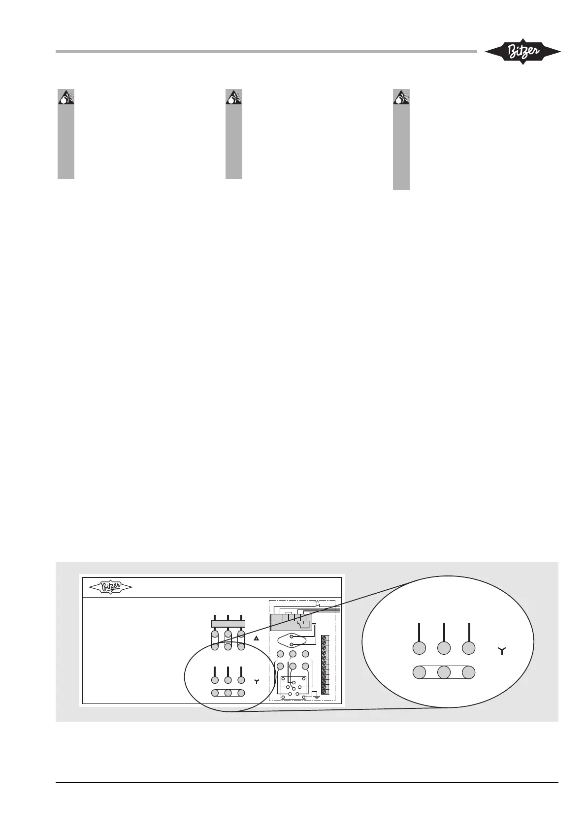
• Anschlussskizze für Verdichternot-
betrieb befindet sich im An schluss -
kastendeckel des Verdich ters
(siehe auch Abb. 11 und 12).
• Kabelverbindung zwischen FU und
Verdichter trennen:
- Im Anschlusskasten des Verdich -
ters das FU-Kabel von den Motor-
bolzen 1/2/3 entfernen.
- Beim Verflüssigungssatz LHV5E/
2DES-3.F1Y: Das geschirmte FU-
Kabel von den Motorbolzen
U/V/W entfernen.
- Kabelenden isolieren.
• Verdichtermotor auf Sternschaltung
(Y) umrüsten:
- Kabelbrücken zwischen den
Motorbolzen entfernen (Dreieck-
schaltung).
- Die Motorbolzen 6/4/5 brücken
(Abb. 11) oder Z/X/Y (Abb. 12)
(Sternschaltung).
Danger!
Electric shock!
Electric charge > 50 μC.
Lethal voltages remain even
after the voltage supply has
been interrupted!
Wait at least 5 minutes after dis-
connecting voltage at all poles
before working at electr(on)ics.
• Make sure that FI, the fans and all
secondary devices are voltage-free.
• Before touching, earth every termi-
nal and cable end.
• To dismount the voltage supply of
the frequency inverter: Remove the
terminals 2/4/6 from contactor K1
in the terminal box of the condens-
ing unit.
• The connecting diagram for emer-
gency service of the compressor is
located in the cover of the terminal
box of the compressor (see also
fig. 11 and 12).
• Disconnect the cable connection
between FI and compressor:
- Remove the FI cable from the
motor pins 1/2/3 in the terminal
box of the compressor.
- With condensing unit LHV5E/
2DES-3.F1Y: Remove the shield-
ed FI cable from U/V/W.
- Insulate the cable ends.
• Change the compressor motor to
star wiring (Y):
- Remove the cable bridges
between the motor pins (delta
wiring):
- Bridge the motor pins 6/4/5 (fig.
11) or Z/X/Y (fig. 12) (star wiring).
Danger !
Électrocution !
Charge électrique > 50 μC!
Tensions mortelles même après le
coupure de l'alimentation électrique !
Après avoir déconnecté tous les
pôles de l'alimentation électrique,
attendre au moins 5 minutes avant
de procéder à des travaux sur le
système électr(on)ique.
• S'assurer, que le CF, les ventilateurs et
tous dispositifs secondaires sont hors
tension.
• Mettre à la terre chaque borne et
chaque extrémité de câble avant de les
toucher.
• Démonter l'alimentation de tension du
CF: Enlever les bornes 2/4/6 du
contacteur K1 dans la boîte de raccor-
dement du groupe de condensation.
• Un schéma de connexion pour le fonc-
tionnement en mode de secours du
compresseur se trouve dans le cou-
vercle de la boîte de raccordement due
compresseur (voir aussi fig. 11 et 12).
• Séparer le raccord de câbles entre CF
et compresseur:
- Enlever le câble du CF des goujons
de moteur 1/2/3 dans la boîte de rac-
cordement.
- En cas du groupe de condensation
LHV5E/2DES-3.F1Y: Enlever le câble
blindé des goujons de moteur U/V/W.
- Isoler les extrêmités des câbles.
• Equiper le moteur du compresseur
d'une connexion en étoile (Y) :
- Enlever les ponts de câble entre les
goujons du moteur (connexion en tri-
angle).
- Ponter les goujons 6/4/5 (fig. 11) ou
Z/X/Y (fig. 12) (connexion en étoile).
KT-203-1
Abb. 12 LHV5E/2DES-3.F1Y:
Aufkleber im Verdichteranschluss-
kastendeckel (CE2-Verdichtertyp)
Fig. 12 LHV5E/2DES-3.F1Y:
View into the compressor terminal
box cover (CE2 compressor model)
E l e k t r i s c h e r A n s c h l u s s
E l e c t r i c a l c o n n e c t i o n
R a c c o r e e n t é l e c t r i q u e
3 7 8 0 0 6 6 8
A c h t u n g !
H i n w e i s e i n d e n B e t r i e b s a n l e i t u n g e n v o n e r -
d i c h t e r u n d F r e q u e n z u m r i c h t e r ( F U ) b e a c h t e n !
K e i n e S p a n n u n g a n P T C - M e s s k r e i s a n l e g e n !
S p a n n u n g s v e r s o r g u n g d e s e r d i c h t e r s ü b e r F U !
( n u r b e i N o t b e t r i e b o h n e F U d i r e k t a m e r d i c h t e r )
A t t e n t i o n !
O b s e r v e r e m a r k s i n t h e O p e r a t i n g I n s t r u c t i o n s
o f c o m p r e s s o r a n d f r e q u e n c y i n v e r t e r ( F I ) !
D o n o t a p p l y a n y v o l t a g e t o P T C c o n t r o l c i r c u i t !
o l t a g e s u p p l y o f c o m p r e s s o r b y F I !
( i n c a s e o f e m e r g e n c y s e r v i c e w i t h o u t F I
v o l t a g e s u p p l y d i r e c t l y a t c o m p r e s s o r )
A t t e n t i o n !
O b s e r v e r l e s i n d i c a t i o n s d a n s l e s i n s t r u c t i o n s
d e s e r v i c e d u c o m p r e s s e u r e t c o n v e r t i s s e u r
d e f r é q u e n c e s ( C F ) !
N e p a s a p p l i q u e r d e t e n s i o n a u c i r c u i t d e c o n t r ô l e C T P !
A l i m e n t e r l e c o m p r e s s e u r a v e c t e n s i o n v i a C F !
( l o r s d e s e r v i c e d e s e c o u r s d i r e c t e m e n t s u r c o m p r e s s e u r )
U
W
X
Y
Z
L 1 L
L 3
N o t b e t r i e b / E e r g e n c y s e r v i c e
S e r v i c e e s e c o u r s
F U - B e t r i e b / V S D O p e r a t i o n
F o n c t i o n n n e e n t a v e c C F
U W
X
Y
Z
L 1 L
L 3
F U / S D / C F
F U
i n t e g r i e r t
/ F
i n t e g r a t e d
/ C F
i n t e g r é
O c t a g o n
®
0 0 V / 5 0 H z
1
1 1
1
7
6
5
4
3
1
U W
X Y
Z
P T C
S E - B 1
L N
B 1
B
1 1 1
1 4
R e s e t
6 0 V / 6 0 H z
U
W
X
Y
Z
L 1 L
L 3
N o t b e t r i e b / E e r g e n c y s e r v i c e
S e r v i c e e s e c o u r s
0 0 V / 5 0 H z
6 0 V / 6 0 H z